PRESSURE VESSEL CALCULATIONS
PROJECT: Broadband Seismometer Pressure Vessel
DATE: 5 March 2001
ANALYST: M. Greise
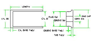
The following calculations are for determining the margin of safety for a pressure vessel at a given
depth. The equations are mostly from Roark's Formulas for Stress and Strain and are referenced
when used. The user must input the dimensions, material properties, and design depth. A factor of
safety will be included in the calculations to determine the minimum margin of safety. The minimum
margin of safety must be greater than zero for the design to be suitable for the depth desired.
The format for this analysis package will be as follows:
A) Input of design parameters including dimensions, material properties, and design depth
B) Calculations for deformation and stresses in cylinders (check for thin wall or thick wall condition)
C) Buckling calculations for cylinders
D) Calculations for deformations and stresses in end plates,
E) Weight calculation
F) Summary of input and list of results including diametral gap, stresses, margins of safety and
weight.
Note: The minimum margin of safety will be determined based upon the lowest margin calculated in
the sections above. Thus, for a give pressure vessel, the maximum working pressure may be limited
by the end plate thickness while for another it may be limited by the length of the cylindrical section. Therefore, if a desired allowable working depth is not reached, the limiting factor needs to be
determined in order to effectively iterate the design to meet the requirements. Also, the diametral
gap must be checked for the different pressures to assure that it falls within the maximum allowable
from the o-ring vendor.
A) Design parameters:
1) Dimensional input:
Enter cylinder dimensions:
Inside Diameter :
Outside Diameter:
O-ring surface diameter:
Length:
Cylinder Base Thickness:
Enter end cap and gland dimensions:
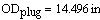
Plug Diameter:
Groove Diameter:
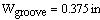
Groove Width:
Groove Base Thickness:
Tab Thickness:
End Cap OD:
Connector Diameter:
End Cap Thickness:
2) Material properties:
Enter material properties:
Material:
Titanium Alloy 6Al-4V
Modulus of elasticity:
Poisson's ratio:
Material density:
Water density:
Yield Stress:
Shear stress:
3) Design depth and resulting pressure:
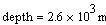
Enter design depth:
Number of pressure steps:
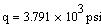
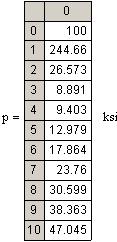
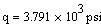
Pressure:
4) Factors of safety to be used:
for buckling:
for stress:
B) Formulas for deformation and stresses in cylinders:
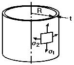
1) Thin walled cylinder calculation:
Reference: Table 28 Formulas for membrane stresses and deformations in thin-walled pressure vessels
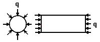
Cylindrical shell; uniform internal or external pressure (ends capped)
Case 1c
Cylindrical shell
Calculated dimensions:
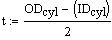
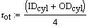
Wall thickness:
Mean radius:
Cylinder Height:
Thin wall stresses:
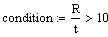
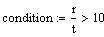
Conditions:
For the expressions in the case to be valid, the following condition must be true (i.e., condition = 1):
Meridional (axial) stress:
Circumferential (hoop) stress:
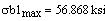
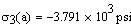
Maximum principal stress:
Change in height:
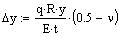
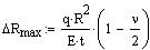
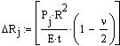
Radial displacement
of circumference:
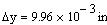
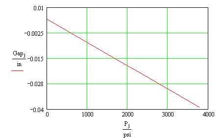
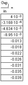
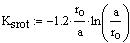
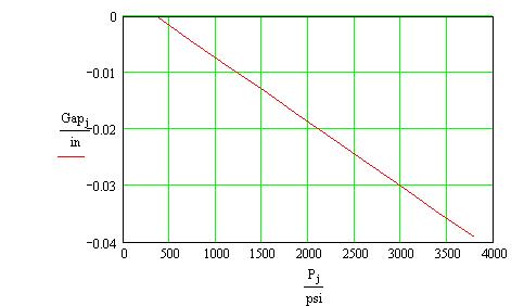
Diametral clearance (extrusion gap):
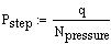
Pressure step:
Diametral extrusion gap:
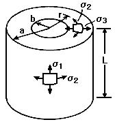
2) Thick walled cylinder calculations:
Table 32 Formulas for thick-walled vessels under internal and external loading
Case 1d
Cylindrical disk or shell; uniform external pressure in all directions, ends capped
Cylindrical disk or shell
Calculated dimensions:
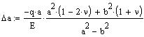
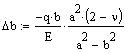
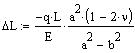
Formulas for change in outer and inner radii, and change in length:
Outer radius:
Inner radius:
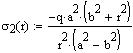
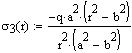
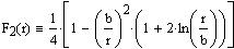
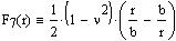
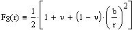
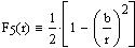
Formulas for normal stresses as a function of radial thickness, r:
radius range variable
Longitudinal stress:
Circumferential stress:
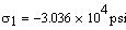
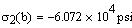
Radial stress:
Maximum principal stress:
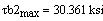
Maximum shear stress (at inner radius, r=b):
Von Mises Stress calculation:
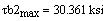
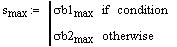
Calculate maximum principal stress based upon wall thickness criteria:
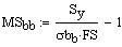
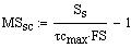
Corresponding margins of safety:
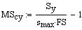
for yield strength:
for shear strength:
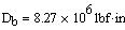
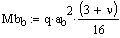
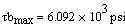
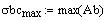
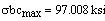
Check stress in bottom:
(Roark Table 24, Case 10:
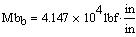
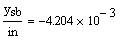
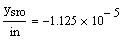
Cylinder Base Thickness:
If assumed simply supported:
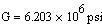
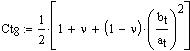
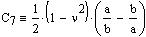
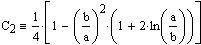
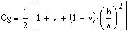
Constants:
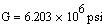
Shear modulus:
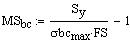
Margin:
C) Buckling calculation for cylinders:
Table 35 Formulas for elastic stability of plates and shells
Case 20a
Thin tube with closed ends under uniform external pressure, lateral and longitudinal; ends held circular
Thin tube with closed ends under uniform external pressure, lateral and longitudinal
Calculated dimensions:
Tube dimensions:
radius:
length:
wall thickness:
Conditions:
For the expressions in the case to be valid, the following condition must be true (i.e., condition = 1):
Critical pressure:
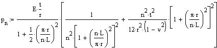
The critical pressure for the initial buckling of a cylinder is:
number of lobes:
critical pressure:
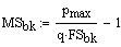
Margin of safety on buckling:
D) Calculations for defections and stresses in end caps:
Table 24 Formulas for shear, moment and deflection of flat circular plates of constant thickness
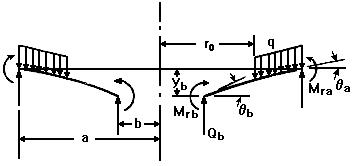
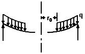
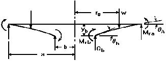
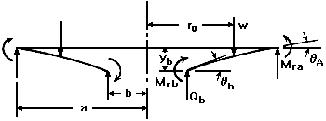
Annular plate with uniformly distributed pressure q over the portion from ro to a; outer edge simply supported
This file corresponds to Case 2a in Roark's Formulas for Stress and Strain.
Annular plate with a uniformly distributed pressure q over the portion from ro to a
Loading assumption:
Outer edge simply supported, inner edge free
Enter dimensions, properties and loading:
Plate dimensions:
thickness:
inner radius:
outer radius:
Radial location of applied load:
Constants:
Shear modulus:
Loading:
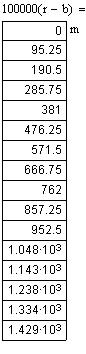
Define r, the range of the radius
(load condition 1a from Table 24)
Deflection:
Deflection at points b and a (inner and outer radius) due to bending:
Deflection at points b and ro due to shear:
Maximum deflection (magnitude):
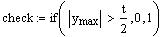
Large deflection check:
Slope:
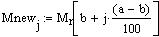
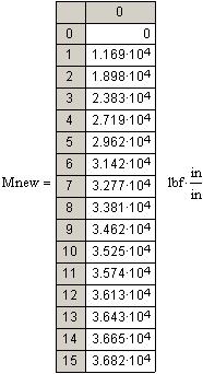
Radial moment:
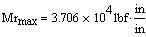
Maximum radial moment (magnitude):
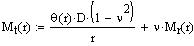
Transverse moment:
Transverse moment at points b and a (inner and outer radius) due to bending:
Maximum tangential moment (magnitude):
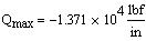
Shear:
Maximum shear (magnitude):
Stress calculations:
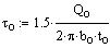
Shear stress:
Radial bending stress:
Maximum radial bending stress (magnitude):
Transverse bending stress:
Maximum tangential bending stress (magnitude):
Stresses in tabs:
For a conservative approach, assume the outer edge of the tabs are free and the inner edge fixed
A) Top tab:
For top tab:
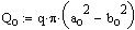
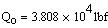
Loading on tab:
Table 24 Formulas for shear, moment and deflection of flat circular plates of constant thickness
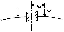
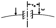
Annular plate with uniform annular line load w at radius ro; outer edge free
Case 1l:
Outer edge free, inner edge fixed
Enter dimensions, properties and loading:
Plate dimensions:
thickness:
outer radius:
inner radius:
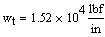
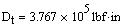
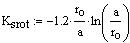
Applied unit load:
Radial location of applied load:
Constants:
Shear modulus:
Define r, the range of the radius:
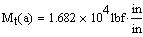
Bending moment about inner fixed edge:
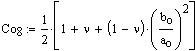
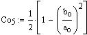
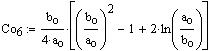
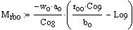
define constants needed:
Bending stress:
Shear:
Shear stress:
B) O-ring groove tab:
For o-ring tab:
Loading on tab:
Table 24 Formulas for shear, moment and deflection of flat circular plates of constant thickness
Annular plate with uniform annular line load w at radius ro; outer edge free
Case 1l:
Outer edge free, inner edge fixed
Enter dimensions, properties and loading:
Plate dimensions:
thickness:
outer radius:
inner radius:
Applied unit load:
Radial location of applied load:
Constants:
Shear modulus:
Define r, the range of the radius:
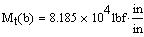
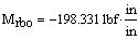
Bending moment about inner fixed edge:
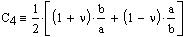
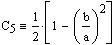
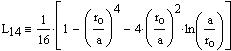
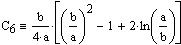
define constants needed:
Bending stress:
Shear:
Shear stress:
Review the maximum values
for deflection, moment, shear and stress:
deflection:
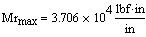
radial bending moment:
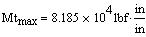
tangential bending moment:
radial bending stress:
tangential bending stress:
tab bending stress:
shear stress:
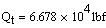
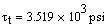
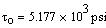
Maximum shear stress:
Maximum bending stress:
Margin of safety for maximum bending stress:
Margin of safety for maximum shear stress:
E) WEIGHT CALCULATION:
Cylinder:
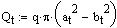
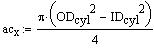
cross sectional area:
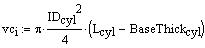
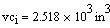
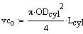
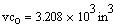
internal volume:
external volume:
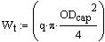
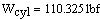
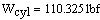
weight:
End Cap:
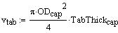
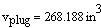
volume:
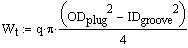
Tab:
Plug:
Cap:
Weight:
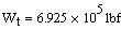
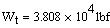
Total weight:
F) SUMMARY SHEET FOR PRESSURE VESSEL CALCULATIONS
Dimensional input:
Cylinder dimensions:
Inside Diameter :
Outside Diameter:
Length:
Cylinder Base Thickness:
End cap and gland dimensions:
Plug Diameter:
Groove Diameter:
Groove Width:
Groove Base Thickness:
Tab Thickness:
End Cap OD:
End Cap Thickness:
Connector Diameter:
Material Input:
Modulus of elasticity:
Poisson's ratio:
Shear stress:
Material density:
Yield Stress:
Depth/working pressure:
Depth:
working pressure:
Stresses in cylinder:
Thin / thick wall assumption
(condition =1 for thin wall)
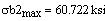
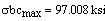
maximum principal stress:
von mises stress:
Shear stress:
(only applicable for thick wall cylinder)
Critical buckling pressure:
Margins of Safety:
for yield strength:
for shear strength:
for buckling:
Stresses in end cap(s) and base
Small deflection assumption:
(check =1 for small deflection)
For end cap:
maximum bending stress:
maximum shear stress:
For base:
maximum bending stress:
Margins of Safety:
for yield strength:
Cap:
Base:
for shear strength:
SUMMARY SHEET FOR PRESSURE VESSEL CALCULATIONS
Diametral clearance between cylinder and end cap(s):
(compare w/ vendors specifications for o-rings)
Weight of cylinder:
(dry)
Weight of cap:
(dry)
Total weight of pressure vessel:
dry:
wet:
Page 1
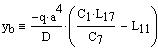
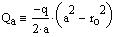
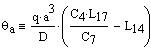
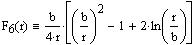
The remainder of the document displays the general plate functions and constants used in the equations above.
Boundary values due to bending:
At the inner edge of the plate:
At the outer edge of the plate:
Due to tangential shear stresses:
End of Section