|
|
November 2002
Synchronizing IEEE 1588 defines a protocol that enables the precise synchronization of clocks in the components of a networked, distributed measurement and control system. John C. Eidson, Agilent
Laboratories Test, measurement, and control systems involve the exchange of information among one or more controllers and numerous sensors and actuators. Correct operation of these systems requires that the temporal relationships of the sensor readings, actuator settings, and controller computations be synchronized. In test and measurement systems, synchronization requirements are dictated by the kinds of correlations and analysis to be applied to the data. In a control system, synchronization requirements are dictated by the parameters of the control loops, characteristics of the plant, and system accuracy requirements. Traditionally, communications in test and measurement systems have been implemented using IEEE 488, while control systems have used a variety of protocols, such as DeviceNet, ControlNet, Profibus, SERCOS, Interbus, and IEEE 1394. If synchronization in these environments is supported, it’s based on the time in which messages are received. In recent years, industries have started to use PCs and Ethernet, which were developed for the general computing environment. Cost, bandwidth, and ease of use have been the driving forces behind this trend. Synchronization requirements in the general computing environment are typically measured anywhere from milliseconds to seconds and are dictated by the application (e.g., distributed file systems, financial transactions, and office computing applications). Many of the world’s networked computers synchronize their clocks using the popular Network Time Protocol (NTP), which operates over Ethernet and the wide area protocols constituting the Internet. Typical synchronization specifications for measurement and control systems range from microseconds, for specialized measurements and control of high-speed processes, to milliseconds, for general measurements and control. The tighter synchronization requirements must be met in computing, networking, and operating environments that differ from a general computing environment. The IEEE work group designed the 1588 standard with these tighter requirements in mind. A Synchronization
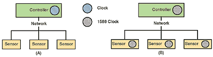
Standard For example, consider the two measurement systems in Figure 1.
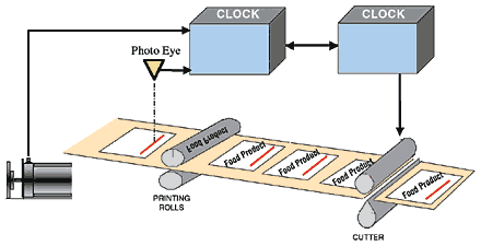
System A is a typical system, with several sensors communicating with a controller via IEEE 488, a sensor/actuator bus, or serial links. The system acquires data from the sensors by polling the controller. The application running on the controller, presumably with the help of the operating system clock, determines the sample timing. The actual sample time depends on the details of the application execution, the communications latency, and the behavior of the sensor, making it difficult to assign a precise time to the sample. The application must also manage the association of multiple data values with their sample times. In contrast, in system B, each smart sensor determines the sample timing based on the time obtained from the local 1588 clock, which is synchronized with its peers in the system. The association of the data values and their time stamps is done locally at each sensor. Sensors that do more than simply acquire raw data are called smart sensors. These sensors perform additional processing of the data before sending them to a controller or other system component. With the inclusion of a common sense of time, smart sensors can perform additional application-level processing relating to synchronization, ordering, and sampling. The controller configures each sensor with the appropriate schedule for acquiring data (e.g., every 25 µs, starting at 10 a.m.) and receives the resulting time-stamped data from each device. But the application software running in the controller need not be concerned with latency and temporal fluctuations in the network and operating system. In system B, the precision of sampling times depends on the synchronization accuracy of the clocks rather than the details of application execution and communications with other components in the system. In such a system, it’s easier to implement independent sampling intervals in each of the sensors or to simultaneously sample to a greater precision than in system A. You can realize a similar advantage in drive and motion applications in which synchronization of time across the entire system can serve as a means of tracking product. If position and velocity data are time stamped throughout the system, you can predict the time an actuator should be asserted to achieve a cutting, printing, or reject function (see Figure 2).
Measurement and control solutions with loose timing requirements can be readily implemented in either system. But as timing requirements tighten and sampling patterns become more complex or rapid, the ability to make use of a common sense of time becomes increasingly attractive. For example, many high-performance systems (e.g., those used in motion control applications) don’t use networked sensors because of the strict synchronization requirements. IEEE 1588 would enable the implementation of network-based sensor systems in such high-performance applications. The IEEE 1588 standard specifies a protocol for synchronizing real-time clocks in a networked system of distributed components. The standard is optimized for:
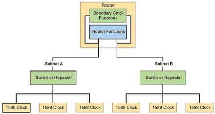
The standard uses networks supporting multicast communications, including but not limited to Ethernet. The capabilities of the individual clocks primarily determine synchronization accuracy. Figure 3 shows a typical distributed system in which each component has a clock synchronized using IEEE 1588.
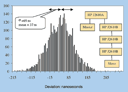
The system consists of subnets A and B, defined by the router, with the components communicating with their peers in the subnet via a switch or repeater. A simple system might consist of a single subnet. The router contains two functional components: the normal routing functions that allow the router to establish subnets according to the underlying communication protocol, and IEEE 1588–defined boundary clock functions. The second group of functions removes the fluctuations in timing that would otherwise be introduced by the router functions. Typically, the protocol will select the best clock in the system, termed the grandmaster clock. In each subnet, the protocol selects the best clock to serve as the master clock of the subnet. In a subnet, all 1588 clocks synchronize to the subnet master, which in turn synchronizes with the grandmaster. In a single subnet system, the master and grandmaster are one and the same. In systems containing multiple boundary clocks, there’s a hierarchy of masters, with the grandmaster at the root. In all cases, the best clock is determined by comparing inherent stability, accuracy, resolution, and other descriptors defined by IEEE 1588. The selection of the grandmaster and master clocks is normally administration free. IEEE 1588 does provide management messages that allow a specific set of clocks to be preferred in the selection process, if required by the application. The time base established by the protocol will be the time base of the grandmaster clock. If the application requires that this time base be coordinated universal time (UTC), the grandmaster clock can be easily synchronized to a recognized source of UTC (e.g., the global positioning satellite system maintained by the Department of Defense). If less accuracy is needed, you can manually set the grandmaster clock using a 1588-defined management message. Master clocks periodically send timing messages to their slaves, providing system synchronization. Less frequently, the process is reversed (with slaves sending timing messages to their masters) to allow automatic calibration for communication latency between the clocks. On average, the 1588 protocol requires about one packet per second on the network. Minimal computing and memory resources are required in nodes hosting a 1588 clock, allowing implementation in relatively simple devices. An indication of the synchronization accuracy to be expected is illustrated in Figure 4.
The data were measured on two clocks implementing an early version of the protocol. In this case, Ethernet was the underlying communications medium. The data show a histogram of the time differences between the second boundaries of two clocks. In this case, the communications path between the master and the slave contains four HP J2610 repeaters, forming an isolated subnet. The measured standard deviation is 69 ns, with a mean of 37 ns. The resolution of the clock is 25 ns. Similar measurements using Ethernet switches rather than repeaters typically yield standard deviations <200 ns. The time synchronization implementation in Figure 4 was an ASIC containing the real-time clock and a simple hardware assist to generate accurate time stamps. The same functionality has also been implemented in a small field programmable gate array (FPGA).
The Status of IEEE
1588 Further technical, application, and implementation details, along with
the latest information on the standard and directions for obtaining a copy
from the IEEE can be found on the IEEE Web site. John C. Eidson is Department Scientist, Agilent Laboratories, Palo Alto, CA; 650-485-4263, john_eidson@agilent.com. R. William Kneifel II, Ph.D., is Engineering Manager, KUKA Development Laboratories, Rochester Hills, MI; 248-844-0560, billkneifel@kukadevlabs.com. Anatoly Moldovansky is Senior Project Engineer, Rockwell Automation, Mayfield Heights, OH; 440-646-5369, amoldovansky@ra.rockwell.com. Stan P. Woods is Project Manager, BioResearch Solutions, Agilent Technologies,
Palo Alto, CA; 650-485-5067, stan_woods@agilent.com.
|
|
|
|
Sensors® and Sensors Expo® are
registered trademarks of Advanstar Communications Inc. Sensors Online Home | Sensors Expo | Contact Us 
|