| Copyright 1998 IEEE. Personal use of this material is
permitted. However, permission to reprint/republish this material for
advertising or promotional purposes or for creating new collective works
for resale or redistribution to servers or lists, or to reuse any
copyrighted component of this work in other works must be obtained from
the IEEE. |
 |
 |
An Overview of CDMA Evolution toward Wideband CDMA
Ramjee Prasad, Delft University of Technology
Tero
Ojanperä, Nokia Telecommunications
Abstract
Third-generation mobile radio networks, often dubbed as 3G, have been
under intense research and discussion recently and will emerge around the year
2000. In the International Telecommunications Union (ITU), third generation
networks are called International Mobile Telecommunications-2000 (IMT-2000), and
in Europe, Universal Mobile Telecommunications System (UMTS). IMT-2000 will
provide a multitude of services, especially multimedia and high-bit-rate packet
data. Wideband code division multiple access (CDMA) has emerged as the
mainstream air interface solution for the third-generation networks. In Europe,
Japan, Korea, and the United States, wideband CDMA systems are currently being
standarized. This article provides a comprehensive introduction to wideband
CDMA. It also provides a review of the wideband CDMA air interface proposals
including WCDMA in Europe and Japan, cdma2000 in the United States, and wideband
CDMA in Korea.
Recently, extensive investigations have
been carried out into the application of a code division multiple access (CDMA)
system as an air interface multiple access scheme for IMT-2000/UMTS
(International Mobile Telecommunications System 2000/Universal Mobile
Telecommunications System). It appears that CDMA is the strongest candidate for
the third-generation wireless personal communication systems. Many research and
development (R&D) projects in the field of wideband CDMA have been going on
in Europe, Japan, the United States, and Korea [1-5]. It seems that wideband
CDMA will be an appropriate answer to the question: "What will be the multiple
access scheme for IMT-2000/UMTS?"
Emerging requirements for higher rate data services and better
spectrum efficiency are the main drivers identified for the third-generation
mobile radio systems. In the ITU, third-generation networks are called IMT-2000,
and in Europe, UMTS. Since 1985, the ITU has been developing IMT-2000,
previously termed Future Public Land Mobile Telephone System (FPLMTS). In ETSI,
UMTS standardization started 1990 when subtechnical committee SMG5 was
established. The main objectives for the IMT-2000 air interface can be
summarized as:
- Full coverage and mobility for 144 Kb/s, preferably 384 Kb/s
- Limited coverage and mobility for 2 Mb/s
- High spectrum efficiency compared to existing systems
- High flexibility to introduce new service
The bit rate targets have been specified according to the
Integrated Services Digital Network (ISDN) rates. The 144-Kb/s data rate
provides the ISDN 2B+D channel, 384 Kb/s provides the ISDN H0 channel, and 1920
Kb/s provides the ISDN H12 channel.1
However, it may be that the main IMT-2000 services are not ISDN-based services.
It has to be noted that these figures have been subject to considerable debate.
Ultimately, market demand will determine what data rates will be offered in
commercial systems. Figure
1 describes the relation between bit rates and mobility for the second- and
third-generation systems.
The targets of
third-generation systems are wide and, depending on the main driver, system
solutions will be different. The maturity of second-generation mobile radio
systems varies, ranging from over 40 percent penetration in Scandinavia to a
very low penetration in developing countries, where the cellular systems are in
the beginning of their lifecycle. Therefore, it is clear that the need to
develop a new system varies, and the different views and needs may result in
several different variants of IMT-2000. In addition, different backward
compatibility requirements influence the technology applied to third-generation
systems.
Main regional standards bodies
have already decided the preferred technology for IMT-2000. The fast development
during recent years has been due to the Japanese initiative. In the beginning of
1997, the Association for Radio Industry and Business (ARIB), a standardization
body responsible for Japan's radio standardization, decided to proceed with
detailed standardization of wideband CDMA. The technology push from Japan
accelerated standardization in Europe and the United States. During 1997 joint
parameters for Japanese and European wideband CDMA proposals were agreed upon.
The air interface is now commonly referred as WCDMA. In January 1998, strong
support behind wideband CDMA led to the selection of WCDMA as the UMTS
terrestrial air interface scheme for FDD frequency bands in ETSI. The selection
of wideband CDMA was also backed by Asian and American GSM operators. For TDD
bands, a time division CDMA (TD-CDMA) concept was selected. In the United States
in March 1998, the TIA (Telecommunications Industry Association) TR45.5
committee, responsible for IS-95 standardization, adopted a framework for
wideband CDMA backward compatible to IS-95, called cdma2000. TR45.3, responsible
for IS-136 standardization, adopted a TDMA-based third-generation proposal,
UWC-136 (Universal Wireless Communications), based on the recommendation from
the UWCC in February 1998. Korea is still considering two wideband CDMA
technologies, one similar to WCDMA and the other similar to cdma2000.
The preferred technology for
third-generation systems depends on technical, political, and business factors.
Technical factors include issues such as provision of required data rates, and
performance. Political factors involve reaching agreement between standards
bodies and taking into account the different starting points of different
countries and regions. On one hand, the investments into the existing systems
motivate a backward compatibility approach. On the other, new business
opportunities or the possibility of changing the current situation might
motivate a new approach.
This article is
organized as follows. The past, present, and future activities of CDMA are
presented in the next section. The following section explains the basic concepts
and elements of CDMA. Then the IS-95 air interface is introduced according to
the new IS-95 standard, followed by a brief discussion of air interface
technologies for third-generation, with a short description of TD-CDMA. Wideband
CDMA schemes are then discussed in great length and conclusions are given in the
final section.
CDMA: Past, Present, and Future
The
origins of spread spectrum are in military field and navigation systems.
Techniques developed to counteract intentional jamming have also proved suitable
for communication through dispersive channels in cellular applications. In this
section we highlight the milestones for CDMA development starting from the 1950s
after the invention of the Shannon theorem [6]. An extensive overview of spread
spectrum history is given in [7].
In
1949, John Pierce wrote a technical memorandum where he described a multiplexing
system in which a common medium carries coded signals that need not be
synchronized. This system can be classified as a time hopping spread spectrum
multiple access system [7]. Claude Shannon and Robert Pierce introduced the
basic ideas of CDMA in 1949 by describing the interference averaging effect and
the graceful degradation of CDMA [8]. In 1950, De Rosa-Rogoff proposed a direct
sequence spread spectrum system and introduced the processing gain equation and
noise multiplexing idea [7]. In 1956, Price and Green filed for the
antimultipath "RAKE" patent [7]. Signals arriving over different propagation
paths can be resolved by a wideband spread spectrum signal and combined by the
RAKE receiver. The near-far problem (i.e., a high interference overwhelming a
weaker spread spectrum signal) was first mentioned in 1961 by Magnuski [7].
For cellular application spread spectrum
was suggested by Cooper and Nettleton in 1978 [9]. During the 1980s Qualcomm
investigated DS-CDMA techniques, which finally led to the commercialization of
cellular spread spectrum communications in the form of the narrowband CDMA IS-95
standard in July 1993. Commercial operation of IS-95 systems started in 1996.
Multiuser detection (MUD) has been subject to extensive research since 1986 when
Verdu formulated an optimum multiuser detection for the additive white Gaussian
noise (AWGN) channel, maximum likelihood sequence estimator (MLSE) [10].
During the 1990s wideband CDMA
techniques with a bandwidth of 5 MHz or more have been studied intensively
throughout the world, and several trial systems have been built and tested [4].
These include FRAMES Multiple Access (FRAMES FMA2) in Europe, Core-A in Japan,
the European/Japanese harmonized WCDMA scheme, cdma2000 in the United States,
and the Telecommunication Technology Association I and II (TTA I and TTA II)
schemes in Korea. Introduction of third-generation wireless communication
systems using wideband CDMA is expected around the year 2000.
Based on the above description, the CDMA era is
divided in three periods: the pioneer CDMA era, the narrowband CDMA era, and the
wideband CDMA era, as shown in Table
1.
CDMA Concepts
In CDMA each user is
assigned a unique code sequence it uses to encode its information-bearing
signal. The receiver, knowing the code sequences of the user, decodes a received
signal after reception and recovers the original data. This is possible since
the crosscorrelations between the code of the desired user and the codes of the
other users are small. Since the bandwidth of the code signal is chosen to be
much larger than the bandwidth of the information-bearing signal, the encoding
process enlarges (spreads) the spectrum of the signal and is therefore also
known as spread-spectrum modulation. The resulting signal is also called a
spread-spectrum signal, and CDMA is often denoted as spread-spectrum multiple
access (SSMA) [13, 1112].
The
spectral spreading of the transmitted signal gives to CDMA its multiple access
capability. It is therefore important to know the techniques necessary to
generate spread-spectrum signals and the properties of these signals. A
spread-spectrum modulation technique must be fulfill two criteria: The
transmission bandwidth must be much larger than the information bandwidth. The
resulting radio-frequency bandwidth is determined by a function other than the
information being sent (so the bandwidth is statistically independent of the
information signal). This excludes modulation techniques like frequency
modulation (FM) and phase modulation (PM).
The ratio of transmitted bandwidth to information bandwidth is
called the processing gain, Gp, of the spread-spectrum
system,
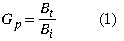
where Bt is the transmission bandwidth and
Bi is the bandwidth of the information-bearing signal.
The receiver correlates the received
signal with a synchronously generated replica of the spreading code to recover
the original information-bearing signal. This implies that the receiver must
know the code used to modulate the data.
Because of the coding and the resulting enlarged bandwidth, SS
signals have a number of properties that differ from the properties of
narrowband signals. The most interesting ones, from the communication systems
point of view, are discussed below. To have a clear understanding, each property
has been briefly explained with the help of illustrations, if necessary, by
applying direct sequence spread-spectrum techniques.
Multiple Access Capability -- If multiple users
transmit a spread-spectrum signal at the same time, the receiver will still be
able to distinguish between the users provided each user has a unique code that
has a sufficiently low cross-correlation with the other codes. Correlating the
received signal with a code signal from a certain user will then only despread
the signal of this user, while the other spread-spectrum signals will remain
spread over a large bandwidth. Thus, within the information bandwidth the power
of the desired user will be larger than the interfering power provided there are
not too many interferers, and the desired signal can be extracted. The multiple
access capability is illustrated in Fig.
2. In Fig.
2a, two users generate a spread-spectrum signal from their narrowband data
signals. In Fig.
2b both users transmit their spread-spectrum signals at the same time. At
the receiver 1 only the signal of user 1 is "despread" and the data recovered.
Protection Against Multipath
Interference -- In a radio channel there is not just one path between a
transmitter and receiver. Due to reflections (and refractions) a signal will be
received from a number of different paths. The signals of the different paths
are all copies of the same transmitted signal but with different amplitudes,
phases, delays, and arrival angles. Adding these signals at the receiver will be
constructive at some of the frequencies and destructive at others. In the time
domain, this results in a dispersed signal. Spread-spectrum modulation can
combat this multipath interference; however, the way in which this is achieved
depends very much on the type of modulation used. In the next section, where
CDMA schemes based on different modulation methods are discussed, we show for
each scheme how multipath interference rejection is obtained.
Privacy -- The transmitted signal can only be
despread and the data recovered if the code is known to the receiver.
Interference Rejection --
Cross-correlating the code signal with a narrowband signal will spread the power
of the narrowband signal thereby reducing the interfering power in the
information bandwidth. This is illustrated in Fig.
3. The spread-spectrum signal (s) receives a narrowband interference (i). At
the receiver the SS signal is "despread" while the interference signal is
spread, making it appear as background noise compared to the despread signal.
Anti-Jamming Capability, Especially
Narrowband Jamming -- This is more or less the same as interference
rejection except the interference is now willfully inflicted on the system. It
is this property, together with the next one, that makes spread-spectrum
modulation attractive for military applications.
Low Probability of Interception (LPI) -- Because of its
low power density, the spread-spectrum signal is difficult to detect and
intercept by a hostile listener.
A
general classification of CDMA is given in Fig.
4. There are a number of modulation techniques that generate spread-spectrum
signals. We briefly discuss the most important ones. Direct sequence
spread-spectrum -- The information-bearing signal is multiplied directly by a
high chip rate code signal. Frequency hopping spread-spectrum -- The carrier
frequency at which the information-bearing signal is transmitted is rapidly
changed according to the code signal Time hopping spread-spectrum -- The
information-bearing signal is not transmitted continuously. Instead the signal
is transmitted in short bursts where the times of the bursts are decided by the
code signal. Hybrid modulation -- Two or more of the above-mentioned SS
modulation techniques can be used together to combine the advantages and, it is
hoped, to combat their disadvantages. Furthermore, it is possible to combine
CDMA with other multiple access methods: TDMA, multicarrier (MC), or multitone
(MT) modulation. In the case of MC-CDMA, spreading is done along the frequency
axis, while for MT-CDMA spreading is done along the time axis. Note that MC-CDMA
and MT-CDMA are based on orthogonal frequency division multiplexing (OFDM).
In the next section the above-mentioned
pure CDMA modulation techniques are used to show the multiple access capability
of CDMA. However, the remainder of the sections will mainly concentrate on
direct sequence (DS)-CDMA and its related subjects.
Spread-Spectrum Multiple Access
Direct Sequence -- In DS-CDMA the modulated
information-bearing signal (the data signal) is directly modulated by a digital,
discrete-time, discrete-valued code signal. The data signal can be either analog
or digital; in most cases it is digital. In the case of a digital signal the
data modulation is often omitted and the data signal is directly multiplied by
the code signal and the resulting signal modulates the wideband carrier. It is
from this direct multiplication that the direct sequence CDMA gets its name.
In Fig.
5 a block diagram of a DS-CDMA transmitter is given. The binary data signal
modulates a RF carrier. The modulated carrier is then modulated by the code
signal. This code signal consists of a number of code bits called "chips" that
can be either +1 or 1. To obtain the desired spreading of the signal, the
chip rate of the code signal must be much higher than the chip rate of the
information signal. For the code modulation various modulation techniques can be
used, but usually some form of phase shift keying (PSK) like binary phase shift
keying (BPSK), differential binary phase shift keying (D-BPSK), quadrature phase
shift keying (QPSK), or minimum shift keying (MSK) is employed.
If we omit the data modulation and use BPSK for the
code modulation, we get the block diagram given in Fig.
6. The DS-SS signal resulting from this transmitter is shown in Fig.
7. The rate of the code signal is called the chip rate; one chip denotes one
symbol when referring to spreading code signals. In this figure, 10 code chips
per information symbol are transmitted (the code chip rate is 10 times the data
rate) so the processing gain is equal to 10.
After transmission of the signal, the receiver (shown in Fig.
8) uses coherent demodulation to despread the SS signal, using a locally
generated code sequence. To be able to perform the despreading operation, the
receiver must not only know the code sequence used to spread the signal, but the
codes of the received signal and the locally generated code must also be
synchronized. This synchronization must be accomplished at the beginning of the
reception and maintained until the whole signal has been received. The code
synchronization/tracking block performs this operation. After despreading a data
modulated signal results, and after demodulation the original data can be
recovered.
In the previous section a
number of advantageous properties of spread-spectrum signals were mentioned. The
most important of those properties from the viewpoint of CDMA is the multiple
access capability, the multipath interference rejection, the narrowband
interference rejection, and with respect to secure/private communication, the
LPI. We explain these four properties for the case of DS-CDMA.
- Multiple access: If multiple users use the channel at the same
time, there will be multiple DS signals overlapping in time and frequency. At
the receiver coherent demodulation is used to remove the code modulation. This
operation concentrates the power of the desired user in the information
bandwidth. If the crosscorrelations between the code of the desired user and
the codes of the interfering users are small, coherent detection will only put
a small part of the power of the interfering signals into the information
bandwidth.
- Multipath interference: If the code sequence has an ideal
autocorrelation function, then the correlation function is zero outside the
interval [Tc,Tc], where
Tc is the chip duration. This means that if the desired
signal and a version that is delayed for more than 2Tc are
received, coherent demodulation will treat the delayed version as an
interfering signal, putting only a small part of the power in the information
bandwidth.
- Narrowband interference: The coherent detection at the receiver
involves a multiplication of the received signal by a locally generated code
sequence. However, as we saw at the transmitter, multiplying a narrowband
signal with a wideband code sequence spreads the spectrum of the narrowband
signal so that its power in the information bandwidth decreases by a factor
equal to the processing gain.
- LPI: Because the direct sequence signal uses the whole signal
spectrum all the time, it will have a very low transmitted power per hertz.
This makes it very difficult to detect a DS signal.
Apart from the above-mentioned properties, DS-CDMA has a
number of other specific properties that we can divide into advantageous (+) and
disadvantageous (-) behavior:
+ The
generation of the coded signal is easy. It can be performed by a simple
multiplication.
+ Since only one carrier
frequency has to be generated, the frequency synthesizer (carrier generator) is
simple.
+ Coherent demodulation of the
DS signal is possible.
+ No
synchronization among the users is necessary.
It is difficult to acquire and maintain the
synchronization of the locally generated code signal and the received signal.
Synchronization has to be kept within a fraction of the chip time.
For correct reception the synchronization
error of locally generated code sequence and the received code sequence must be
very small, a fraction of the chip time. This combined with the nonavailability
of large contiguous frequency bands practically limits the bandwidth to
1020 MHz.
The power received
from users close to the base station is much higher than that received from
users further away. Since a user continuously transmits over the whole
bandwidth, a user close to the base will constantly create a lot of interference
for users far from the base station, making their reception impossible. This
near-far effect can be solved by applying a power control algorithm so that all
users are received by the base station with the same average power. However this
control proves to be quite difficult.
Frequency Hopping -- In frequency hopping CDMA, the
carrier frequency of the modulated information signal is not constant but
changes periodically. During time intervals T the carrier frequency
remains the same, but after each time interval the carrier hops to another (or
possibly the same) frequency. The hopping pattern is decided by the code signal.
The set of available frequencies the carrier can attain is called the
hop-set.
The frequency occupation
of an FH-SS system differs considerably from a DS-SS system. A DS system
occupies the whole frequency band when it transmits, whereas an FH system uses
only a small part of the bandwidth when it transmits, but the location of this
part differs in time.
The difference
between the FH-SS and the DH-SS frequency usage is illustrated in Fig.
9. Suppose an FH system is transmitting in frequency band 2 during the first
time period. A DS system transmitting in the same time period spreads its signal
power over the whole frequency band so the power transmitted in frequency band 2
will be much less than that of the FH system. However, the DS system transmits
in frequency band 2 during all time periods while the FH system only uses this
band part of the time. On average, both systems will transmit the same power in
the frequency band.
The block diagram
for an FH-CDMA system is given in Fig.
10. The data signal is baseband modulated. Using a fast frequency
synthesizer that is controlled by the code signal, the carrier frequency is
converted up to the transmission frequency.
The inverse process takes place at the receiver. Using a
locally generated code sequence, the received signal is converted down to the
baseband. The data is recovered after (baseband) demodulation. The
synchronization/tracking circuit ensures that the hopping of the locally
generated carrier synchronizes to the hopping pattern of the received carrier so
that correct despreading of the signal is possible.
Within frequency hopping CDMA a distinction is made that is
based on the hopping rate of the carrier. If the hopping rate is (much) greater
than the symbol rate, one speaks of a fast frequency hopping (F-FH). In this
case the carrier frequency changes a number of times during the transmission of
one symbol, so that one bit is transmitted in different frequencies. If the
hopping rate is (much) smaller than the symbol rate, one speaks of slow
frequency hopping (S-FH). In this case multiple symbols are transmitted at the
same frequency.
The occupied bandwidth
of the signal on one of the hopping frequencies depends not only on the
bandwidth of the information signal but also on the shape of the hopping signal
and the hopping frequency. If the hopping frequency is much smaller than the
information bandwidth (which is the case in slow frequency hopping), then the
information bandwidth is the main factor that decides the occupied bandwidth.
If, however, the hopping frequency is much greater than the information
bandwidth, the pulse shape of the hopping signal will decide the occupied
bandwidth at one hopping frequency. If this pulse shape is very abrupt
(resulting in very abrupt frequency changes), the frequency band will be very
broad, limiting the number of hop frequencies. If we make sure that the
frequency changes are smooth, the frequency band at each hopping frequency will
be about 1/Th times the frequency bandwidth, where
Th is equal to the hopping frequency. We can make the
frequency changes smooth by decreasing the transmitted power before a frequency
hop and increasing it again when the hopping frequency has changed.
As has been done for the DS-CDMA, we discuss the
properties of FH-CDMA with respect to multiple access capability, multipath
interference rejection, narrowband interference rejection, and probability of
interception.
Multiple Access --
It is easy to visualize how the F-FH and S-FH CDMA obtain their multiple access
capability. In the F-FH one symbol is transmitted in different frequency bands.
If the desired user is the only one to transmit in most of the frequency bands,
the received power of the desired signal will be much higher than the
interfering power and the signal will be received correctly.
In the S-FH multiple symbols are transmitted at one
frequency. If the probability of other users transmitting in the same frequency
band is low enough, the desired user will be received correctly most of the
time. For those times that interfering users transmit in the same frequency
band, error-correcting codes are used to recover the data transmitted during
that period.
Multipath
Interference -- In the F-FH CDMA the carrier frequency changes a number of
times during the transmission of one symbol. Thus, a particular signal frequency
will be modulated and transmitted on a number of carrier frequencies. The
multipath effect is different at the different carrier frequencies. As a result,
signal frequencies that are amplified at one carrier frequency will be
attenuated at another carrier frequency and vice versa. At the receiver the
responses at the different hopping frequencies are averaged, thus reducing the
multipath interference. Since usually noncoherent combining is used, this is not
as effective as the multipath interference rejection in a DS-CDMA system, but it
still gives quite an improvement.
Narrowband Interference -- Suppose a narrowband signal
is interfering on one of the hopping frequencies. If there are
Gp hopping frequencies (where Gp is the
processing gain), the desired user will (on the average) use the hopping
frequency where the interferer is located 1/Gp percent of the
time. The interference is therefore reduced by a factor Gp.
LPI -- The difficulty in
intercepting an FH signal lies not in its low transmission power. During a
transmission, it uses as much power per hertz as a continuous transmission. But
the frequency at which the signal is going to be transmitted is unknown, and the
duration of the transmission at a particular frequency is quite small.
Therefore, although the signal is more readily intercepted than a DS signal, it
is still a difficult task to perform.
Apart from the above-mentioned properties, the FH-CDMA has a
number of other specific properties that we can divide into advantageous (+) and
disadvantageous (-) behavior:
+
Synchronization is much easier with FH-CDMA than with DS-CDMA. With FH-CDMA
synchronization has to be within a fraction of the hop time. Since spectral
spreading is not obtained by using a very high hopping frequency but by using a
large hop-set, the hop time will be much longer than the chip time of a DS-CDMA
system. Thus, an FH-CDMA system allows a larger synchronization error.
+ The different frequency bands that an
FH signal can occupy do not have to be contiguous because we can make the
frequency synthesizer easily skip over certain parts of the spectrum. Combined
with the easier synchronization, this allows much higher spread-spectrum
bandwidths.
+ The probability of
multiple users transmitting in the same frequency band at the same time is
small. A user transmitting far from the base station will be received by it even
if users close to the base station are transmitting, since those users will
probably be transmitting at different frequencies. Thus, the near-far
performance is much better than that of DS.
+ Because of the larger possible bandwidth a FH system can
employ, it offers a higher possible reduction of narrowband interference than a
DS system.
A highly sophisticated
frequency synthesizer is necessary.
An abrupt change of the signal when changing frequency
bands will lead to an increase in the frequency band occupied. To avoid this,
the signal has to be turned off and on when changing frequency.
Coherent demodulation is difficult because of
the problems in maintaining phase relationships during hopping.
Time Hopping -- In time hopping CDMA the data
signal is transmitted in rapid bursts at time intervals determined by the code
assigned to the user. The time axis is divided into frames, and each frame is
divided into M time slots. During each frame the user will transmit in
one of the M time slots. Which of the M time slots is transmitted
depends on the code signal assigned to the user. Since a user transmits all of
its data in one, instead of M time slots, the frequency it needs for its
transmission has increased by a factor M. A block diagram of a TH-CDMA
system is given in Fig.
11. Figure
12 shows the time-frequency plot of the TH-CDMA systems. Comparing Fig.
12 with Fig.
9, we see that the TH-CDMA uses the whole wideband spectrum for short
periods instead of parts of the spectrum all of the time. Following the same
procedure as for the previous CDMA schemes, we discuss the properties of TH-CDMA
with respect to multiple access capability, multipath interference rejection,
narrowband interference rejection, and probability of interception. Multiple
access -- The multiple access capability of TH-SS signals is acquired in the
same manner as that of the FH-SS signals; namely, by making the probability of
users' transmissions in the same frequency band at the same time small. In the
case of time hopping all transmissions are in the same frequency band, so the
probability of more than one transmission at the same time must be small. This
is again achieved by assigning different codes to different users. If multiple
transmissions do occur, error-correcting codes ensure that the desired signal
can still be recovered. If there is synchronization among the users, and the
assigned codes are such that no more than one user transmits at a particular
slot, then the TH-CDMA reduces to a TDMA scheme where the slot in which a user
transmits is not fixed but changes from frame to frame. Multipath interference
-- In the time hopping CDMA, a signal is transmitted in reduced time. The
signaling rate, therefore, increases and dispersion of the signal will now lead
to overlap of adjacent bits. Therefore, no advantage is to be gained with
respect to multipath interference rejection. Narrowband interference -- A
TH-CDMA signal is transmitted in reduced time. This reduction is equal to
1/Gp, where Gp is the processing gain. At
the receiver we will only receive an interfering signal during the reception of
the desired signal. Thus, we only receive the interfering signal
1/Gp percent of the time, reducing the interfering power by a
factor Gp. LPI -- With TH-CDMA the frequency at which a user
transmits is constant but the times at which a user transmits are unknown, and
the durations of the transmissions are very short. Particularly when multiple
users are transmitting, this makes it difficult for an intercepting receiver to
distinguish the beginning and end of a transmission and to decide which
transmissions belong to which user.
Apart from the above-mentioned properties, the TH-CDMA has a
number of other specific properties that we can divide into advantageous (+) and
disadvantageous (-) behavior:
+
Implementation is simpler than that of FH-CDMA.
+ It is a very useful method when the transmitter is
average-power limited but not peak-power limited since the data are transmitted
is short bursts at high power.
+ As with
the FH-CDMA, the near-far problem is much less of a problem since TH-CDMA is an
avoidance system, so most of the time a terminal far from the base station
transmits alone, and is not hindered by transmissions from stations close by.
It takes a long time before the
code is synchronized, and the time in which the receiver has to perform the
synchronization is short.
If
multiple transmissions occur, a large number of data bits are lost, so a good
error-correcting code and data interleaving are necessary.
Hybrid Systems -- The hybrid CDMA systems include all
CDMA systems that employ a combination of two or more of the above-mentioned
spread-spectrum modulation techniques or a combination of CDMA with some other
multiple access technique. By combining the basic spread-spectrum modulation
techniques, we have four possible hybrid systems: DS/FH, DS/TH, FH/TH, and
DS/FH/TH; and by combining CDMA with TDMA or multicarrier modulation we get two
more: CDMA/TDMA and MC-CDMA.
The idea of
the hybrid system is to combine the specific advantages of each of the
modulation techniques. If we take, for example, the combined DS/FH system, we
have the advantage of the anti-multipath property of the DS system combined with
the favorable near-far operation of the FH system. Of course, the disadvantage
lies in the increased complexity of the transmitter and receiver. For
illustration purposes, we give a block diagram of a combined DS/FH CDMA
transmitter in Fig.
13.
The data signal is first spread
using a DS code signal. The spread signal is then modulated on a carrier whose
frequency hops according to another code sequence. A code clock ensures a fixed
relation between the two codes.
Basic DS-CDMA Elements
In this
section, we review the fundamental elements for understanding direct sequence
CDMA and its application into third-generation systems, namely, RAKE receiver,
power control, soft handover, interfrequency handover, and multiuser detection.
RAKE Receiver -- A
spread-spectrum signal waveform is well matched to the multipath channel. In a
multipath channel, the original transmitted signal reflects from obstacles such
as buildings, and mountains, and the receiver receives several copies of the
signal with different delays. If the signals arrive more than one chip apart
from each other, the receiver can resolve them. Actually, from each multipath
signal's point of view, other multipath signals can be regarded as interference
and they are suppressed by the processing gain. However, a further benefit is
obtained if the resolved multipath signals are combined using RAKE receiver.
Thus, the signal waveform of CDMA signals facilitates utilization of multipath
diversity. Expressing the same phenomenon in the frequency domain means that the
bandwidth of the transmitted signal is larger than the coherence bandwidth of
the channel and the channel is frequency selective (i.e., only part of the
signal is affected by the fading).
RAKE
receiver consists of correlators, each receiving a multipath signal. After
despreading by correlators, the signals are combined using, for example, maximal
ratio combining. Since the received multipath signals are fading independently,
diversity order and thus performance are improved. Fig.
14 illustrates the principle of RAKE receiver. After spreading and
modulation the signal is transmitted and it passes through a multipath channel,
which can be modeled by a tapped delay line (i.e., the reflected signals are
delayed and attenuated in the channel). In Fig.
14 we have three multipath components with different delays (*1, *2, and *3)
and attenuation factors (a1, a2, and a3), each corresponding to a different
propagation path. The RAKE receiver has a receiver finger for each multipath
component. In each finger, the received signal is correlated by a spreading
code, which is time-aligned with the delay of the multipath signal. After
despreading, the signals are weighted and combined. In Fig.
14, maximal ratio combining is used, that is, each signal is weighted by the
path gain (attenuation factor). Due to the mobile movement the scattering
environment will change, and thus, the delays and attenuation factors will
change as well. Therefore, it is necessary to measure the tapped delay line
profile and to reallocate RAKE fingers whenever there is need. Small-scale
changes, less than one chip, are taken care of by a code tracking loop, which
tracks the time delay of each multipath signal.
Power Control -- In the uplink of a DS-CDMA system, the
requirement for power control is the most serious negative point. The power
control problem arises because of the multiple access interference. All users in
a DS-CDMA system transmit the messages by using the same bandwidth at the same
time and therefore users interfere with one another. Due to the propagation
mechanism, the signal received by the base station from a user terminal close to
the base station will be stronger than the signal received from another terminal
located at the cell boundary. Hence, the distant users will be dominated by the
close user. This is called the near-far effect. To achieve a considerable
capacity, all signals, irrespective of distance, should arrive at the base
station with the same mean power. A solution to this problem is power control,
which attempts to achieve a constant received mean power for each user.
Therefore, the performance of the transmitter power control (TPC) is one of the
several dependent factors when deciding on the capacity of a DS-CDMA system.
In contrast to the uplink, in the
downlink all signals propagate through the same channel and thus are received by
a mobile station with equal power. Therefore, no power control is required to
eliminate near-far problem. The power control is, however, required to minimize
the interference to other cells and to compensate against the interference from
other cells. The worst-case situation for a mobile station occurs when the
mobile station is at the cell edge, equidistant from three base stations.
However, the interference from other cells does not vary very abruptly.
In addition being useful against
interfering users, power control improves the performance of DS-CDMA against
fading channel by compensating the fading dips. If it followed the channel
fading perfectly, power control would turn a fading channel into AWGN channel by
eliminating the fading dips completely.
There exist two types of power control principles: open loop
and closed loop. The open loop power control measures the interference
conditions from the channel and adjusts the transmission power accordingly.
However, since the fast fading does not correlate between uplink and downlink,
open loop power control will achieve the right power target only on average.
Therefore, closed loop power control is required. The closed loop power control
measures the signal-to-interference ratio (SIR) and sends commands to the
transmitter on the other end to adjust the transmission power.
Soft Handover -- In soft handover a mobile
station is connected to more than one base station simultaneously. Soft handover
is used in CDMA to reduce the interference into other cells and to improve
performance through macro diversity. Softer handover is a soft handover between
two sectors of a cell.
Neighboring cells
of a cellular system using either FDMA or TDMA do not use the frequencies used
by the given cell (i.e., there is spatial separation between cells using the
same frequencies). This is called the frequency reuse concept. Because of the
processing gain, such spatial separation is not needed in CDMA, and frequency
reuse factor of one can be used. Usually, a mobile station performs a handover
when the signal strength of a neighboring cell exceeds the signal strength of
the current cell with a given threshold. This is called hard handover.
Since in a CDMA system the neighboring cell frequencies are the same as in the
given cell, this type of approach would cause excessive interference into the
neighboring cells and thus a capacity degradation. In order to avoid this
interference, an instantaneous handover from the current cell to the new cell
would be required when the signal strength of the new cell exceeds the signal
strength of the current cell. This is not, however, feasible in practice. The
handover mechanism should always allow the mobile station to connect into a
cell, which it receives with the highest power (i.e., with the lowest pathloss).
Since in soft handover the mobile station is connected to either two or more
base stations, its transmission power can be controlled according to the cell,
which the mobile station receives with the highest signal strength. A mobile
station enters the soft handover state when the signal strength of neighboring
cell exceeds a certain threshold but is still below the current base station's
signal strength.
Fortunately, the signal
structure of CDMA is well suited for the implementation of soft handover. This
is because in the uplink, two or more base stations can receive the same signal
because of the reuse factor of one; and in the downlink the mobile station can
coherently combine the signals from different base stations since it sees them
as just additional multipath components. This provides an additional benefit
called macro diversity (i.e., the diversity gain provided by the reception of
one or more additional signals). A separate channel called pilot is usually used
for the signal strength measurements for handover purposes.
In the downlink, however, soft handover creates more
interference to the system since the new base station now transmits an
additional signal for the mobile station. It is possible that the mobile station
cannot catch all the energy that the base station transmits due to a limited
number of RAKE fingers. Thus, the gain of soft handover in the downlink depends
on the gain of macro diversity and the loss of performance due to increased
interference. Fig.
15 illustrates the soft handover principle with two base stations involved.
In the uplink the mobile station signal is received by the two base stations,
which, after demodulation and combining, pass the signal forward to the
combining point, typically to the base station controller (BSC). In the downlink
the same information is transmitted via both base stations, and the mobile
station receives the information from two base stations as separate multipath
signals and can therefore combine them.
Interfrequency Handover -- The third-generation CDMA
networks will have multiple frequency carriers in each cell, and a hot-spot cell
could have a larger number of frequencies than neigboring cells. Furthermore, in
hierarchical cell structures, micro cells will have a different frequency than
the macro cell overlaying the micro cells. Therefore, an efficient procedure is
needed for a handover between different frequencies. A blind handover used by
second-generation CDMA does not result in an adequate call quality. Instead, the
mobile station has to be able to measure the signal strength and quality of an
another carrier frequency, while still maintaining the connection in the current
carrier frequency. Since a CDMA transmission is continuous, there are no idle
slots for the interfrequency measurement/ as in the TDMA-based systems.
Therefore, compressed mode and dual receiver have been proposed as a solution to
interfrequency handover [13]. In the compressed mode, measurements slots are
created by transmitting the data of a frame, for example, with a lower spreading
ratio during a shorter period, and the rest of the frame is utilized for the
measurements on other carriers. The dual receiver can measure other frequencies
without affecting the reception of the current frequency.
Multiuser Detection -- The current CDMA receivers are
based on the RAKE receiver principle, which considers other users' signals as
interference. However, in an optimum receiver all signals would be detected
jointly or interference from other signals would be removed by subtracting them
from the desired signal. This is possible because the correlation properties
between signals are known (i.e., the interference is deterministic not random).
The capacity of a direct sequence CDMA
system using RAKE receiver is interference limited. In practice this means that
when a new user, or interferer, enters the network, other users' service quality
will go below the acceptable level. The more the network can resist interference
the more users can be served. Multiple access interference that disturbs a base
or mobile station is a sum of both intra- and inter-cell interference.
Multiuser detection (MUD), also called
joint detection and interference cancellation (IC), provides a means of reducing
the effect of multiple access interference, and hence increases the system
capacity. In the first place MUD is considered to cancel only the intra-cell
interference, meaning that in a practical system the capacity will be limited by
the efficiency of the algorithm and the inter-cell interference.
In addition to capacity improvement, MUD alleviates
the near/far problem typical to DS-CDMA systems. A mobile station close to a
base station may block the whole cell traffic by using too high a transmission
power. If this user is detected first and subtracted from the input signal, the
other users do not see the interference.
Since optimal multiuser detection is very complex and in
practice impossible to implement for any reasonable number of users, a number of
suboptimum multiuser and interference cancellation receivers have been
developed. The suboptimum receivers can be divided into two main categories:
linear detectors and interference cancellation. Linear detectors apply a linear
transform into the outputs of the matched filters that are trying to remove the
multiple access interference (i.e., the interference due to correlations between
user codes). Examples of linear detectors are decorrelator and linear minimum
mean square error (LMMSE) detectors. In interference cancellation multiple
access interference is first estimated and then subtracted from the received
signal. Parallel interference cancellation (PIC) and successive (serial)
interference cancellation (SIC) are examples of interference cancellation.
For a more detailed treatment of
multiuser detection and interference cancellation, refer to [1, 1417].
IS-95 CDMA
In this section, we
describe the features of the IS-95 air interface according to the new IS-95B
standard, with a focus on the new downlink and uplink channel structure [18].2
Main air interface parameters, downlink and uplink channel structures, power
control principles, and speech coding are discussed. For a more detailed
treatment of the IS-95A standard, refer to [11] and for a theoretical analysis
of IS-95 air interface solutions, refer to [12].
The IS-95 air interface standard, after the first revision in
1995, was termed IS-95A [19]; it specifies the air interface for cellular,
800-Mhz frequency band. ANSI J-STD-008 specifies the PCS version (i.e., the air
interface for 1900 MHz). It differs from IS-95A primarily in the frequency plan
and in call processing related to subscriber station identity, such as paging
and call origination. TSB74 specifies the Rate Set 2 (14.4 Kb/s) standard.
IS-95B merges the IS-95A, ANSI J-STD-008 [20], and TSB74 standards, and, in
addition, it specifies the high-speed data operation using up to eight parallel
codes, resulting in a maximum bit rate of 115.2 Kb/s. In addition to these air
interface specifications, the IS-97 [21] and IS-98 [22] standards specify the
minimum performance specifications for the mobile and base station,
respectively.
Table
2 lists the main parameters of the IS-95 air interface. Carrier spacing of
the system is 1.25 MHz. Practical deployment has shown that 3 CDMA carriers can
be fitted into 5 MHz bandwidth due to required guard bands. Network is
synchronous within few microseconds. This facilitates use of the same long code
sequence with different phase offsets as pilot sequences. However, an external
reference signal such as GPS is needed.
Downlink Channel Structure
Figure
16a and Fig.
16b show the downlink physical channel structure. The pilot channel, the
paging channel, and the synchronization channel3
are common control channels and traffic channels are dedicated channels. A
common channel is a shared channel, and a dedicated channel is solely allocated
for the use of a single user. Data to be transmitted on synchronization, paging,
and traffic channels are first grouped into 20-ms frames, convolutionally
encoded, repeated to adjust the data rate, and interleaved. Then the signal is
spread with an orthogonal Walsh code at a rate of 1.2288 Mc/s, split into the I
and Q channels, and, prior to baseband filtering, spread with long PN sequences
at a rate of 1.2288 Mc/s.
A mobile
station uses the pilot channel for coherent demodulation, acquisition, time
delay tracking, power control measurements, and as an aid for the handover. In
order to obtain a reliable phase reference for coherent demodulation, the pilot
channel is transmitted with higher power than the traffic channels. Typically
about 20 percent of the radiated power on the downlink is dedicated to the pilot
signal. After obtaining phase and code synchronization, the mobile station
acquires synchronization information (data rate of the paging channel, time of
the base station's pilot PN sequence with respect to the system time) from the
synchronization channel. Since the synchronization channel frame has the same
length as the pilot sequence, acquisition of the synchronization channel takes
place easily. The synchronization channel operates at a fixed rate of 1.2 Kb/s.
The paging channel is used to page a mobile station. The paging channel has a
fixed data rate of 9.6 or 4.8 Kb/s.
Each
forward traffic channel contains one fundamental code channel and may contain
one to seven supplemental code channels. The traffic channel has two different
rate sets. The rate set 1 supports data rates of 9.6, 4.8, 2.4, and 1.2 Kb/s and
the rate set 2 supports 14.4, 7.2, 3.6, and 1.8 Kb/s. Only the full rate (9.6 or
14.4 Kb/s) may be utilized on the supplemental code channels. The mobile station
always supports the rate set 1 and it may support the rate set 2. To achieve
equal power levels at the base station receiver, the base station measures the
received signal and adjusts each mobile station's power levels accordingly. The
20-ms frame is divided into 16 power control groups with a duration of 1.25 ms.
One power control bit is multiplexed in for the fundamental code channel for
each power control group.
The
transmitted data is encoded by a convolutional code with a constraint length of
9. The generator functions for this code are 753 (octal) and 561 (octal). For
the synchronization channel, the paging channels, and rate set 1 on the traffic
channel, a convolutional code with a rate of 1/2 is used. For the rate set 2, an
effective code rate of 3/4 is achieved by puncturing two out of every six
symbols after the symbol repetition.
Since the data rate on different channels varies, symbol
repetition is used to achieve a fixed data rate prior to interleaving. For the
synchronization channel, each convolutionally encoded symbol shall be repeated
once (i.e., each symbol occurs two consecutive times). For the paging channel,
each code symbol at the 4800-b/s rate shall be repeated once. The code symbol
repetition rate on the forward traffic channels varies with data rate. Code
symbols are not repeated for the 14.4- and 9.6-Kb/s data rates. Each code symbol
at the 7.2- and 4.8-Kb/s data rates is repeated once, at the 3.6 and 2.4 Kb/s
data rates three times, and at the 1.8- and 1.2-Kb/s data rates seven times.
In the downlink, three types of
spreading codes are used. Walsh codes of length 64 at a fixed chip rate of
1.2288 Mc/s separate the physical channels. The Walsh function consisting of all
zeros W0 (Walsh code number 0) is used for the pilot channel, W1-W7 are used for
paging channels (unused paging channel codes can be used for traffic channels).
The synchronization channel is W32, and traffic channels are W8 to W31 and W33
to W63. A pair of long M-sequences of length 16,767 (2151) is
used for quadrature spreading, one for the I channel and one for the Q channel.
Quaternary spreading is used to obtain better interference averaging. Since the
pilot channel Walsh function is all zeros, this pair of sequences also forms the
pilot code. Different cells and sectors are distinguished with the different
phase offsets of this code.
A long
pseudo random sequence with a period of 2421 is used for base
band data scrambling (i.e., to encrypt the signal on the paging and traffic
channels). It is decimated from a 1.2288-Mc/s rate down to 19.2 Kb/s. The long
pseudo noise sequence is the same used in the uplink for user separation, and it
is generated by a modulo-2 inner product of a 42-bit mask and the 42-bit state
vector of the sequence generator.
Uplink Channel Structure
As
depicted in Fig.
17, Fig.
18, Fig.
19, and Fig.
20, the uplink has two physical channels: a traffic channel, which is a
dedicated channel, and a common access channel. A traffic channel consists of a
single fundamental code channel and zero through seven supplemental code
channels. Similar to the downlink, traffic channels always support the rate set
1 data rates and may support the rate set 2 data rates. The supplemental code
channel can only use the full rates (9.6 or 14.4 Kb/s). Data transmitted on the
uplink channels are grouped into 20-ms frames, convolutionally encoded, block
interleaved, and modulated by 64-ary orthogonal modulation. Then, prior to
baseband filtering, the signal is spread with a long PN sequence at a rate of
1.2288 Mc/s, split into the I and Q channels, and spread with in-phase and
quadrature spreading sequences.
The
access channel is used by a mobile station to initiate a call, to respond to a
paging channel message from the base station, and for a location update. Each
access channel is associated with a downlink paging channel, and consequently
there can be up to seven access channels. The access channel supports fixed data
rate operation at 4.8 Kb/s.
The
transmitted information is encoded using a convolutional code with constraint
length 9 and the same generator polynomials as in the downlink. For the access
channel and rate set 1 on the traffic channels, the convolutional code rate is
1/3. For rate set 2 on the traffic channels, a code rate of 1/2 is used. Similar
to the downlink, code symbols output from the convolutional encoder are repeated
before being interleaved when the data rate is lower than 9.6 Kb/s for rate set
1 and 14.4 Kb/s for rate set 2. However, the repeated symbols are not actually
transmitted. They are masked out according to a masking pattern generated by the
data burst randomizer to save transmission power. For the access channel, which
has a fixed data rate of 4.8 Kb/s, each code symbol is repeated once. In
contrast to the traffic channel, the repeated code symbols are transmitted.
The coded symbols are grouped into
6-symbol groups. These groups are then used to select one of 64 possible Walsh
symbols (i.e., a 64-ary orthogonal modulation is carried out to obtain good
performance for noncoherent modulation). After the orthogonal modulation, the
transmission rate is 307.2 Kb/s. The reason to use the non-coherent modulation
is the difficulty in obtaining good phase reference for coherent demodulation in
the uplink. It should be noted how the Walsh codes are used differently in the
uplink and downlink. In the downlink, they were used for channelization, while
in the uplink they are used for orthogonal modulation.
Each code channel in a traffic channel and each access channel
are identified by a different phase of a pseudo-random M-sequence with a length
of 242. The in-phase and quadrature spreading is performed by the
same pair of M-sequences (length 215) as in the downlink (now
augmented by one chip).
Power Control
IS-95 has three
different power control mechanisms. In the uplink, both open loop and fast
closed loop power control are employed. In the downlink, a relatively slow power
control loop controls the transmission power.
Open Loop Power Control -- The open loop power control
has two main functions: it adjusts the initial access channel transmission power
of the mobile station and compensates large abrupt variations in the pathloss
attenuation. The mobile station determines an estimate of the pathloss between
the base station and mobile station by measuring the received signal strength at
the mobile using an automatic gain control (AGC) circuitry, which gives a rough
estimate of the propagation loss for each user. The smaller the received power,
the larger the propagation loss, and vice-versa. The transmit power of the
mobile station is determined from the equation:
mean output power (dBm)
= mean input power (dBm) (2)
+ offset power + parameters
The offset power for the 800-MHz band mobiles (band class 0)
is 73 and for the 1900-MHz band mobiles (band class 1) 76 [18]. The
parameters are used to adjust the open-loop power control for different cell
sizes and different cell effective radiated powers (ERP) and receiver
sensitivities [23]. These parameters are initially transmitted on the
synchronization channel.
The open loop
power control principle is described in Fig.
21. Since the distance (d1) of mobile station 1 to the base station (BTS) is
shorter than the distance of mobile station 2 (d2) to the BTS, the signal
received by the mobile station 1 has a smaller propagation loss. Assume that the
mean input power of the mobile station 1 is 70 dBm (100 pW)4
and the mean input power of the mobile station 2 is 90 dBm (1 pW). For band
class 0 mobiles with no correction parameters, the mobile station transmission
power to achieve equal received powers at the base station can be calculated
from (2.2) to be 17 dBm (50 mW) and 7 dBm (200 µW), respectively.
Closed Loop Power Control --
Since the IS-95 uplink and downlink have a frequency separation of 20 MHz, their
fading processes are not strongly correlated. Even though the average power is
approximately the same, the short term power is different, and therefore, the
open loop power control cannot compensate for the uplink fading. To account for
the independence of the Rayleigh fading in the uplink and downlink, the base
station also controls the mobile station transmission power. Fig.
22 illustrates the closed loop power control. The base station measures the
received SIR5
over a 1.25-ms period, equivalent to six modulation symbols, compares that to
the target SIR, and decides whether the mobile station transmission power needs
to be increased or decreased. The power control bits are transmitted on the
downlink fundamental code channel every 1.25 ms (i.e., with a transmission rate
of 800 Hz) by puncturing the data symbols. The placement of a power control bit
is randomized within the 1.25-ms power control group. The transmission occurs in
the second power control group following the corresponding uplink traffic
channel power control group in which the SIR was estimated.6
Since the power control commands are
transmitted uncoded, their error ratio is fairly high, on the order of 5
percent. However, since the loop is of delta modulation type (i.e., power is
adjusted continuously up or down) this is not critical. The mobile station
extracts the power control bits commands and adjusts its transmission power
accordingly. The adjustment step is a system parameter and can be 0.25, 0.5, or
1.0 dB. The dynamic range for the closed loop power control is ±24 dB. The
composite dynamic range for open and closed loop power control is ±32 dB for
mobile stations operating in band class 0, and ±40 dB for mobile stations
operating in band class 1 [18]. The typical standard deviation of the power
control error due to the closed loop is on the order of 1.1 to 1.5 dB [12].
The SIR required to produce a certain
bit error rate varies according to radio environment and depends on the amount
and type of multipath. Therefore, IS-95 employs an outer loop that adjusts the
target SIR. The base station measures the signal quality (bit error rate), and
based on that determines the target SIR. However, this outer loop will increase
the power control error, resulting in a total standard deviation of 1.5 to 2.5
dB [12].
Downlink Slow Power
Control -- The base station controls its transmission power to a given
mobile station according to the pathloss and interference situation. The main
purpose of the slow downlink power control is to improve the performance of
mobile stations at a cell edge where the signal is weak and the interfering base
station signals are strong. The downlink power control mechanism is as follows.
The base station periodically reduces the transmitted power to the mobile
station. The mobile station measures the frame error ratio (FER). When the FER
exceeds a predefined limit, typically 1 percent, the mobile station requests
additional power from the base station. This adjustment occurs every 15 to 20
ms. The dynamic range of the downlink power control is only ±6 dB.
Both periodic and threshold reporting may be enabled
simultaneously, either one of them may be enabled, or both forms of reporting
may be disabled at any given time.
Speech Codecs and
Discontinuous Transmission (DTX)
IS-95 has three speech codecs, 8-Kb/s QCELP, 8-Kb/s EVRC, and
13 Kb/s. The higher rate codec was developed to provide better voice quality,
but due to its higher bit rate it reduces the system capacity. Therefore, the
enhanced variable rate codec (EVRC) operating at 8 Kb/s was developed. Speech
codecs are four-rate code excited linear prediction codecs (CELP). The vocoder
rates of the 8-Kb/s codecs are 1, 2, 4, and 8 Kb/s corresponding to channel
rates of 1.2, 2.4, 4.8, and 9.6 Kb/s. The 13-Kb/s codec uses a 14.4 Kb/s channel
rate. Since the system capacity is directly proportional to interference,
reduction of the transmitted data rate results in better capacity. In IS-95,
data rate reduction is implemented with discontinuous transmission (DTX), which
is realized by gating the transmitter in pseudo-random fashion on and off. The
drawback of this approach is that it creates pulsed interference.
Air Interface Technologies
for Third Generation
In the search for the most appropriate multiple access
technology for third-generation wireless systems, a number of new multiple
access schemes have been proposed (e.g, wideband CDMA schemes, UWC-136
TDMA-based scheme, and TD-CDMA). This section presents a detailed description of
Wideband CDMA schemes and briefly reveiws a TD-CDMA scheme.
Wideband CDMA
Wideband CDMA has a
bandwidth of 5 MHz or more. The nominal bandwidth for all third-generation
proposals is 5 MHz. There are several reasons for choosing this bandwidth.
First, data rates of 144 and 384 Kb/s, the main targets of third-generation
systems, are achievable within 5 MHz bandwidth with a reasonable capacity. Even
a 2-Mb/s peak rate can be provided under limited conditions. Second, lack of
spectrum calls for reasonably small minimum spectrum allocation, especially if
the system has to be deployed within the existing frequency bands occupied
already by second-generation systems. Third, the 5-MHz bandwidth can resolve
(separate) more multipaths than narrower bandwidths, increasing diversity and
thus improving performance. Larger bandwidths of 10, 15, and 20 MHz have been
proposed to support higher data rates more effectively.
Several wideband CDMA proposals have been made for
third-generation wireless systems. They can be characterized by the following
new advanced properties:
- Provision of multirate services
- Packet data
- Complex spreading
- A coherent uplink using a user dedicated pilot
- Additional pilot channel in the downlink for beamforming
- Seamless interfrequency handover
- Fast power control in the downlink
- Optional multiuser detection
The third-generation air interface standardization for the
schemes based on CDMA seems to focus on two main types of wideband CDMA: network
asynchronous and synchronous. In network asynchronous schemes the base stations
are not synchronized, while in network synchronous schemes the base stations are
synchronized to each other within a few microseconds. As discussed, there are
three network asynchronous CDMA proposals: WCDMA in ETSI and in ARIB, and TTA II
in Korea have similar parameters. A network synchronous wideband CDMA scheme has
been adopted by TR45.5 (cdma2000) and is being considered by Korea (TTA I). The
section to follow describes the different wideband CDMA schemes in detail.
Hybrid CDMA/TDMA
In the ETSI air
interface selection, the TDD solution was decided to be based on the TD-CDMA
principles. In this section the original TD-CDMA scheme is presented. The role
of CDMA in TD-CDMA is to multiplex the different channels within a timeslot. The
spreading ratio is small, and, thus, if more than a few users are desired per
frame, joint detection is needed to remove the intracell interference.
Therefore, in a fully loaded system the spreading does not help against the
interference from other cells. Also, the slow power control results in large
variations in the received signal levels, and thus, joint detection is needed.
Since the joint detection is a mandatory feature, it is more critical compared
to wideband CDMA. However, if the number of users is small, the complexity of
joint detection may not be excessive. The parameters of TD-CDMA are listed in Table
3.
Wideband CDMA Schemes
This section
presents the wideband CDMA air interface being developed by the standardization
organizations in Europe, Japan, the United States, and Korea for
third-generation communication systems. Fig.
23 illustrates the different schemes and their relations to standards bodies
and to each other.
The third-generation
air interface standardization for the schemes based on CDMA seems to focus on
two main types of wideband CDMA: network asynchronous and network synchronous.
In network asynchronous schemes the base stations are not synchronized, while in
network synchronous schemes the base stations are synchronized to each other
within a few microseconds. There are three network asynchronous CDMA proposals:
WCDMA7
in ETSI and ARIB, and TTA II8
wideband CDMA in Korea have similar parameters [5]. In addition, T1P1 in the
United States has joined the development of WCDMA. TR46.1 in the United States
is also developing a wideband CDMA scheme, Wireless Multimedia & Messaging
Services (WIMS), which has been recently harmonized with WCDMA. A network
synchronous wideband CDMA scheme has been proposed by TR45.5 (cdma2000) and is
being considered by Korea (TTA I9)
[5]. All schemes are geared towards the IMT-2000 radio transmission technology
selection process in ITU-R TG8/1. In addition to the above main wideband CDMA
schemes, we introduce two more that are interesting from a wideband CDMA
development perspective. These are CODIT and IS-665 W-CDMA.
Several attempts have been made to harmonize the
different wideband CDMA approaches in search of a unified global air interface.
However, due to the evolution of current systems and the strong commercial
interests of their supporters, at the moment it seems that there will be at
least two wideband CDMA standards for third-generation. It should be noted that
several changes of parameters have occurred during the development of these
proposals and the detailed concepts and standards will be developed during 1998
and 1999. In this section we try to reflect the latest information available in
the literature. The ITU radio transmission technology descriptions of different
wideband CDMA schemes can be found in [2531] (available from the ITU Web site.
We first describe the technical approaches for the network
asynchronous and synchronous schemes and discuss the reasoning for 5-MHz
bandwidth for third-generation wideband CDMA. WCDMA and cdma2000 are described
in detail covering carrier spacing and deployment scenarios, physical channels,
spreading, multirate schemes (variable data rates), packet data, and handover.
The main technical parameters for the TTA I and TTA II schemes are presented and
their differences compared to WCDMA and cdma2000 are highlighted. Finally, the
CODIT and IS-665 schemes are briefly described.
Technical Approaches
In the
following, we discuss the main technical approaches of WCDMA and cdma2000. These
differences apply to the TTA I and TTA II as well. The main differences between
WCDMA and cdma2000 systems are chip rate, downlink channel structure, and
network synchronization. cdma2000 uses a chip rate of 3.6864 Mc/s for the 5-MHz
band allocation with the direct spread downlink and a 1.2288-Mc/s chip rate for
the multicarrier downlink [5]. WCDMA uses direct spread with a chip rate of
4.096 Mc/s. The multicarrier approach is motivated by a spectrum overlay of
cdma2000 with existing IS-95 carriers. Similar to IS-95B, the spreading codes of
cdma2000 are generated using different phase shifts of the same M-sequence. This
is possible because of the synchronous network operation. Since WCDMA has an
asynchronous network, different long codes rather than different phase shifts of
the same code are used for the cell and user separation. The code structure
further impacts how code synchronization, cell acquisition, and handover
synchronization are performed.
The
nominal bandwidth for all third-generation proposals is 5-MHz. There are several
reasons for choosing this bandwidth. First, data rates of 144 and 384 Kb/s are
achievable within 5-MHz bandwidth for third-generation systems and can be
provided with reasonable capacity. Even 2-Mb/s peak rate can be provided under
limited conditions. Second, lack of spectrum calls for reasonably small minimum
spectrum allocation, especially if the system has to be deployed within the
existing frequency bands already occupied by the second-generation systems.
Third, the large 5-MHz bandwidth can resolve more multipaths than a narrower
bandwidth, thus increasing diversity and improving performance. Larger
bandwidths of 10, 15, and 20 MHz have been proposed to support highest data
rates more effectively.
WCDMA
The WCDMA scheme has been
developed as a joint effort between ETSI and ARIB during the second half of 1997
[32]. The ETSI WCDMA scheme has been developed from the FMA2 scheme in Europe
[3339] and the ARIB WCDMA from the Core-A scheme in Japan [4045]. The
uplink of the WCDMA scheme is based mainly on the FMA2 scheme, and the downlink
on the Core-A scheme. In this section, we present the main technical features of
the ARIB/ETSI WCDMA scheme. Table
4 lists the main parameters of WCDMA.
Carrier Spacing and Deployment Scenarios -- The carrier
spacing has a raster of 200 kHz and can vary from 4.2 to 5.4 MHz. The different
carrier spacings can be used to obtain suitable adjacent channel protections
depending on the interference scenario. Fig.
24 shows an example for the operator bandwidth of 15 MHz with three cell
layers. Larger carrier spacing can be applied between operators than within one
operator's band in order to avoid inter-operator interference. Interfrequency
measurements and handovers are supported by WCDMA to utilize several cell layers
and carriers.
Logical Channels --
WCDMA basically follows the ITU Recommendation M.1035 in the definition of
logical channels [46]. The following logical channels are defined for WCDMA. The
three available common control channels are:
- Broadcast control channel (BCCH) carries system and cell specific
information
- Paging channel (PCH) for messages to the mobiles in the paging area
- Forward access channel (FACH) for massages from the base station to the
mobile in one cell.
In addition,
there are two dedicated channels:
- Dedicated control channel (DCCH) covers the two dedicated control channel
stand-alone dedicated channel (SDCCH) and associated control channel (ACCH)
- Dedicated traffic channel (DTCH) for point-to-point data transmission in
the uplink and downlink
Physical Channels
Uplink Physical Channels. There are two dedicated
channels and one common channel on the uplink. User data is transmitted on the
dedicated physical data channel (DPDCH), and control information is transmitted
on the dedicated physical data channel (DPDCH). The random access channel is a
common access channel.
Fig.
25 shows the principle frame structure of the uplink DPDCH. Each DPDCH frame
on a single code carries 160 x 2k bits (16 x
2k Kb/s), where k = 0,1, ..., 6, corresponding to a
spreading factor of 256/2k with the 4.096-Mc/s chip rate.
Multiple parallel variable rate services (= dedicated logical traffic and
control channels) can be time multiplexed within each DPDCH frame. The overall
DPDCH bit rate is variable on a frame-by-frame basis.
In most cases, only one DPDCH is allocated per connection, and
services are jointly interleaved sharing the same DPDCH. However, multiple
DPDCHs can also be allocated (e.g. to avoid a too low spreading factor at high
data rates).
The dedicated physical
control channel (DPCCH) is needed to transmit pilot symbols for coherent
reception, power control signaling bits, and rate information for rate
detection. Two basic solutions for multiplexing physical control and data
channels are time multiplexing and code multiplexing. A combined IQ and code
multiplexing solution (dual-channel QPSK) is used in WCDMA uplink to avoid
electromagnetic compatibility (EMC) problems with discontinuous transmission
(DTX).
The major drawback of the time
multiplexed control channel are the EMC problems that arise when DTX is used for
user data. One example of a DTX service is speech. During silent periods no
information bits need to be transmitted, which results in pulsed transmission as
control data must be transmitted in any case. This is illustrated in Fig.
26. Because the rate of transmission of pilot and power control symbols is
on the order of 1 to 2 kHz, they cause severe EMC problems to both external
equipment and terminal interiors. This EMC problem is more difficult in the
uplink direction since mobile stations can be close to other electrical
equipment, like hearing aids.
The
IQ/code multiplexed control channel is shown in Fig.
27. Now, since pilot and power control are on a separate channel, no
pulse-like transmission takes place. Interference to other users and cellular
capacity remains the same as in the time multiplexed solution. In addition,
link-level performance is the same in both schemes if the energy allocated to
the pilot and the power control bits is the same.
The structure of the random access burst is shown in Fig.
28. The random access burst consists of two parts, a preamble part of length
16 x 256 chips (1 ms) and a data part of variable length.
The WCDMA random access scheme is based on a slotted ALOHA
technique with the random access burst structure shown in Fig.
28. Before the transmission of a random access request, the mobile terminal
should carry out the following tasks:
- Achieve chip, slot, and frame synchronization to the target base station
from the synchronization channel (SCH) and obtain information about the
downlink scrambling code also from the SCH
- Retrieve information from BCCH about the random access code(s) used in the
target cell/sector
- Estimate the downlink path loss, which is used together with a signal
strength target to calculate the required transmit power of the random access
request
It is possible to transmit
a short packet together with a random access burst without settting up a
scheduled packet channel. No separate access channel is used for packet traffic
related random access, but all traffic shares the same random access channel.
More than one random access channel can be used if the random access capacity
requires such an arrangement. The performance of the selected solution is
presented in [47].
Downlink Physical
Channels. In the downlink, there are three common physical channels. The
primary and secondary common control physical channels (CCPCH) carry the
downlink common control logical channels (BCCH, PCH, and FACH); the SCH provides
timing information and is used for handover measurements by the mobile station.
The dedicated channels (DPDCH and DPCCH)
are time multiplexed. The EMC problem caused by discontinuous transmission is
not considered difficult in downlink since (1) there are signals to several
users transmitted in parallel and at the same time and (2) base stations are not
so close to other electrical equipment, like hearing aids.
In the downlink, time multiplexed pilot symbols are used for
coherent detection. Since the pilot symbols are connection dedicated, they can
be used for channel estimation with adaptive antennas as well. Furthermore, the
connection dedicated pilot symbols can be used to support downlink fast power
control. In addition, a common pilot time multiplexed in the BCCH channel can be
used for coherent detection.
The primary
CCPCH carries the BCCH channel and a time multiplexed common pilot channel. It
is of fixed rate and is mapped to the DPDCH in the same way as dedicated traffic
channels. The primary CCPCH is allocated the same channelization code in all
cells. A mobile terminal can thus always find the BCCH, once the base station's
unique scrambling code has been detected during the initial cell search.
The secondary physical channel for
common control carries the PCH and FACH in time multiplex within the super frame
structure. The rate of the secondary CCPCH may be different for different cells
and is set to provide the required capacity for PCH and FACH in each specific
environment. The channelization code of the secondary CCPCH is transmitted on
the primary CCPCH.
The SCH consists of
two subchannels, the primary and secondary SCHs. Fig.
29 illustrates the structure of the SCH. The SCH applies short code masking
to minimize the acquisition time of the long code [48]. The SCH is masked with
two short codes (primary and secondary SCH). The unmodulated primary SCH is used
to acquire the timing for the secondary SCH. The modulated secondary SCH code
carries information about the long code group to which the long code of the BS
belongs. In this way, the search of long codes can be limited to a subset of all
the codes.
The primary SCH consists of
an unmodulated code of length 256 chips, which is transmitted once every slot.
The primary synchronization code is the same for every base station in the
system and is transmitted time aligned with the slot boundary, as illustrated in
Fig.
29.
The secondary SCH consists of
one modulated code of length 256 chips, which is transmitted in parallel with
the primary SCH. The secondary synchronization code is chosen from a set of 16
different codes depending on to which of the 32 different code groups the base
station downlink scrambling code csc belongs.
The secondary SCH is modulated with a binary sequence of
length 16 bits, which is repeated for each frame. The modulation sequence, which
is the same for all base stations, has good cyclic autocorrelation properties.
The multiplexing of the SCH with the
other downlink physical channels (DPDCH/DPCCH and CCPCH) is illustrated in Fig.
30. The SCH is transmitted only intermittently (one codeword per slot), and
it is multiplexed with the DPDCH/DPCCH and CCPCH after long code scrambling is
applied on DPDCH/DPCCH and CCPCH. Consequently, the SCH is nonorthogonal to the
other downlink physical channels.
Spreading -- The WCDMA scheme employs long spreading
codes. Different spreading codes are used for cell separation in the downlink
and user separation in the uplink. In the downlink, Gold codes of length
218 are used, but they are truncated to form a cycle of a 10-ms
frame. The total number of available scrambling codes is 512, divided into 32
code groups with 16 codes in each group to facilitate a fast cell search
procedure. In the uplink, either short or long spreading (scrambling codes) are
used. The short codes are used to ease the implementation of advanced multiuser
receiver techniques; otherwise long spreading codes can be used. Short codes are
VL-Kasami codes of length 256 and lond codes are Gold sequences of length
241, but the latter are truncated to form a cycle of a 10-ms frame.
For channelization, orthogonal codes are
used. Orthogonality between the different spreading factors can be achieved by
the tree-structured orthogonal codes.
IQ/code multiplexing leads to parallel transmission of two
channels, and therefore, attention must be paid to modulated signal
constellation and related peak-to-average power ratio (crest factor). By using
the complex spreading circuit shown in Fig.
31, the transmitter power amplifier efficiency remains the same as for QPSK
transmission in general.
Moreover, the
efficiency remains constant irrespective of the power difference G
between DPDCH and DPCCH. This can be explained with Fig.
32, which shows the signal constellation for IQ/code multiplexed control
channel with complex spreading. In the middle constellation with G = 0.5
all eight constellation points are at the same distance from the origin. The
same is true for all values of G. Thus, signal envelope variations are
very similar to the QPSK transmission for all values of G. The IQ/code
multiplexing solution with complex scrambling results in power amplifier output
backoff requirements that remain constant as a function of power difference.
Furthermore, the achieved output backoff is the same as for one QPSK signal.
Multirate -- Multiple services of
the same connection are multiplexed on one DPDCH. Multiplexing may take place
either before or after the inner or outer coding, as illustrated in Fig.
33. After service multiplexing and channel coding, the multiservice data
stream is mapped to one DPDCH. If the total rate exceeds the upper limit for
single code transmission, several DPDCHs can be allocated.
A second alternative for service multiplexing would be to map
parallel services to different DPDCHs in a multicode fashion with separate
channel coding/interleaving. With this alternative scheme, the power, and
consequently the quality of each service, can be separately and independently
controlled. The disadvantage is the need for multicode transmission, which will
have an impact on mobile station complexity. Multicode transmission sets higher
requirements for the power amplifier linearity in transmission, and more
correlators are needed in reception.
For
BER = 103 services, convolutional coding of 1/3 is used. For high bit
rates a code rate of 1/2 can be applied. For higher quality service classes
outer Reed-Solomon coding is used to reach the 106 BER level.
Retransmissions can be utilized to guarantee service quality for non real-time
packet data services.
After channel
coding and service multiplexing, the total bit rate can be almost arbitrary. The
rate matching adapts this rate to the limited set of possible bit rates of a
DPDCH. Repetition or puncturing is used to match the coded bit stream to the
channel gross rate. The rate matching for uplink and downlink are introduced
below.
For the uplink, rate matching to
the closest uplink DPDCH bit rate is always based on unequal repetition (a
subset of the bits repeated) or code puncturing. In general, code puncturing is
chosen for bit rates less than (20 percent above the closest lower DPDCH bit
rate. For all other cases, unequal repetition is performed to the closest higher
DPDCH bit rate. The repetition/puncturing patterns follow a regular predefined
rule (i.e., only the amount of repetition/puncturing needs to be agreed on). The
correct repetition/puncturing pattern can then be directly derived by both the
transmitter and receiver side.
For the
downlink, rate matching to the closest DPDCH bit rate, using either unequal
repetition or code puncturing, is only made for the highest rate (after channel
coding and service multiplexing) of a variable rate connection and for
fixed-rate connections. For lower rates of a variable rate connection, the same
repetition/puncturing pattern as for the highest rate is used, and the remaining
rate matching is based on discontinuous transmission where only a part of each
slot is used for transmission. This approach is used in order to simplify the
implementation of blind rate detection in the mobile station.
Packet Data -- WCDMA has two different types
of packet data transmission possibilities. Short data packets can be appended
directly to a random access burst. This method, called common channel packet
transmission, is used for short infrequent packets, where the link
maintenance needed for a dedicated channel would lead to an unacceptable
overhead.
When using the uplink common
channel, a packet is appended directly to a random access burst. Common channel
packet transmission is typically used for short, infrequent packets, where the
link maintenance needed for a dedicated channel would lead to unacceptable
overhead. Also, the delay associated with a transfer to a dedicated channel is
avoided. Note that for common channel packet transmission only open loop power
control is in operation. Common channel packet transmission should therefore be
limited to short packets that only use a limited capacity. Figure
34 illustrates packet transmission on a common channel.
Larger or more frequent packets are transmitted on a
dedicated channel. A large single packet is transmitted using a single-packet
scheme where the dedicated channel is released immediately after the packet
has been transmitted. In a multipacket scheme the dedicated channel is
maintained by transmitting power control and synchronization information between
subsequent packets.
Handover --
Base stations in WCDMA need not be synchronized, and therefore, no external
source of synchronization, like GPS, is needed for the base stations.
Asynchronous base stations must be considered when designing soft handover
algorithms and when implementing position location services. These two aspects
are considered in this section.
Before
entering soft handover, the mobile station measures observed timing differences
of the downlink SCHs from the two base stations. The structure of SCH is
presented in a section to follow, "Physical Channels." The mobile station
reports the timing differences back to the serving base station. The timing of a
new downlink soft handover connection is adjusted with a resolution of one
symbol (i.e., the dedicated downlink signals from the two base stations are
synchronized with an accuracy of one symbol). That enables the mobile RAKE
receiver to collect the macro diversity energy from the two base stations.
Timing adjustments of dedicated downlink channels can be carried out with a
resolution of one symbol without losing orthogonality of downlink codes.
Interfrequency Handovers.
Interfrequency handovers are needed for utilization of hierarchical cell
structures; macro, micro, and indoor cells. Several carriers and interfrequency
handovers may also be used for taking care of high capacity needs in hot spots.
Interfrequency handovers will be needed also for handovers to second-generation
systems, like GSM or IS-95. In order to complete interfrequency handovers, an
efficient method is needed for making measurements on other frequencies while
still having the connection running on the current frequency. Two methods are
considered for interfrequency measurements in WCDMA:
- Dual receiver
- Slotted mode
The dual receiver
approach is considered suitable especially if the mobile terminal employs
antenna diversity. During the interfrequency measurements, one receiver branch
is switched to another frequency for measurements, while the other keeps
receiving from the current frequency. The loss of diversity gain during
measurements needs to be compensated for with higher downlink transmission
power. The advantage of the dual receiver approach is that there is no break in
the current frequency connection. Fast closed loop power loop is running all the
time.
The slotted mode approach depicted
in Fig.
35 is considered attractive for the mobile station without antenna
diversity. The information normally transmitted during a 10-ms frame is
compressed time either by code puncturing or by changing the FEC rate.
Inter-operability Between GSM and
WCDMA. The handover between the WCDMA system and the GSM system, offering
worldwide coverage already today, has been one of the main design criteria taken
into account in the WCDMA frame timing definition. The GSM compatible multiframe
structure, with a superframe multiple of 120 ms, allows similar timing for
intersystem measurements as in the GSM system itself. Apparently the needed
measurement interval does not need to be as frequent as for GSM terminal
operating in a GSM system, as intersystem handover is less critical from
intra-system interference point of view. Rather, the compatibility in timing is
important that when operating in WCDMA mode, a multimode terminal is able to
catch the desired information from the synchronization bursts in the
synchronization frame on a GSM carrier with the aid of frequency correction
burst. This way the relative timing between a GSM and WCDMA carriers is
maintained similar to the timing between two asynchronous GSM carriers. The
timing relation between WCDMA channels and GSM channels is indicated in Fig.
36, where the GSM traffic channel and WCDMA channels use similar 120 ms
multiframe structure. The GSM frequency correction channel (FCCH) and GSM
synchronization channel (SCH) use one slot out of the eight GSM slots in the
indicated frames with the FCCH frame with one time slot for FCCH always
preceding the SCH frame with one time slot for SCH as indicated in the Fig.
36. Further details on GSM common channel structures can be found in [49].
A WCDMA terminal can do the measurements
either by requesting the measurement intervals in a form of slotted mode where
there are breaks in the downlink transmission or then it can perform the
measurements independently with a suitable measurement pattern. With independent
measurements the dual receiver approach is used instead of the slotted mode
since the GSM receiver branch can operate independently of the WCDMA receiver
branch.
For smooth interoperation
between the systems, information needs to be exchanged between the systems, in
order to allow WCDMA base station to notify the terminal of the existing GSM
frequencies in the area. In addition, more integrated operation is needed for
the actual handover where the current service is maintained, taking naturally
into account the lower data rate capabilities in GSM when compared to UMTS
maximum data rates reaching all the way to 2 Mb/s.
The GSM system is likewise expected to be able to indicate
also the WCDMA spreading codes in the area to make the cell identification
simpler and after that the existing measurement practises in GSM can be used for
measuring the WCDMA when operating in GSM mode.
As the WCDMA does not rely on any superframe structure as with
GSM to find out synchronization, the terminal operating in GSM mode is able to
obtain the WCDMA frame synchronization once the WCDMA base station scrambling
code timing is acquired. The base station scrambling code has 10-ms period and
its frame timing is synchronized to WCDMA common channels.
cdma2000
Within standardization
committee TIA TR45.5, the subcommittee TR45.5.4 was responsible for the
selection of the basic cdma2000 concept. Like for all the other wideband CDMA
schemes, the goal has been to provide data rates that meet the IMT-2000
performance requirements of at least 144 Kb/s in a vehicular environment, 384
Kb/s in a pedestrian environment, and 2048 Kb/s in an indoor office environment.
The main focus of standardization has been providing 144 Kb/s and 384 Kb/s with
approximately 5-MHz bandwidth. The main parameters of cdma2000 are listed in Table
5.
Bandwidth and Deployment
Scenarios -- In the following we highlight the channel structures of
cdma2000. Currently there exist two main alternatives for the downlink:
multicarrier and direct spread options. The multicarrier approach maintains
orthogonality between the cdma2000 and IS-95 carriers [51]. In the downlink this
is more important because the power control cannot balance the interfering
powers between different layers, as it can in the uplink. As illustrated in Fig.
37, transmission on the multicarrier downlink (nominal 5-MHz band) is
achieved by using three consecutive IS-95B carriers10
where each carrier has a chip rate of 1.2288 Mc/s. For the direct spread option,
transmission on the downlink is achieved by using a nominal chip rate of 3.6864
Mc/s. The multicarrier approach has been proposed since it might provide easier
an overlay with the existing IS-95 systems. This is because without multipath it
retains orthogonality with existing IS-95 carriers. However, in certain
conditions the spectrum efficiency of multicarrier is 5 to 10 percent worse than
direct spread since it can resolve a smaller number of multipath components
[51]. Regardless of the downlink solution, if an operator has a 5-MHz allocation
and if at least 1.25 MHz is already in use, the implementation of either the
multicarrier or the direct spread overlay could be challenging [51].
The starting point for bandwidth design of cdma2000
has been the PCS spectrum allocation in the United States. The PCS spectrum is
allocated in 5-MHz blocks (D, E, and F blocks) and 15-MHz blocks (A, B, and C
blocks). One 3.6864-Mc/s carrier can be deployed within 5-MHz spectrum
allocation including guardbands. For the 15-MHz block, three 3.6864 Mc/s
carriers plus two 1.2288-Mc/s carriers can be deployed. For a 10-MHz block two
3.6864-Mc/s carriers plus one 1.2288-Mc/s carrier can be deployed [52].
Logical Channels -- At the time
of writing, the logical channels for cdma2000 were still under development. The
reader is referred to the latest standards documents in TIA [29].
Physical channels
Uplink Physical Channels. In the uplink, there are four
different dedicated channels. The fundamental and supplemental channels carry
user data. A dedicated control channel, with a frame length 5 or 20 ms, carries
control information such as measurement data, and a pilot channel is used as a
reference signal for coherent detection. The pilot channel also carries time
multiplexed power control symbols. Figure
38 illustrates the different uplink dedicated channels separated by Walsh
codes.
The reverse access channel
(R-ACH) and the reverse common control channel (R-CCCH) are common channels used
for communication of layer 3 and MAC layer messages. The R-ACH is used for
initial access, while the R-CCCH is used for fast packet access.
The fundamental channel conveys voice, signaling,
and low rate data. Basically it will operate at low FER (around 1 percent). The
fundamental channel supports basic rates of 9.6 Kb/s and 14.4 Kb/s and their
corresponding subrates (i.e., Rate Set 1 and 2 of IS-95). The fundamental
channel will always operate in soft handover mode. The fundamental channel does
not operate in a scheduled manner; thus permitting the mobile station to
transmit acknowledgments or short packets without scheduling. This reduces delay
and the processing load due to scheduling [52]. Its main difference compared to
the IS-95 voice channel is that discontinuous transmission is implemented using
repetition coding rather than gated transmission.
The supplemental channel provides high data rates. The uplink
supports one or two supplemental channels. If only one supplemental channel is
transmitted, then the Walsh code (+) is used on the first supplemental
channel, and if two supplemental channels are transmitted then the Walsh code
(++) is used. A repetition scheme is used for variable data rates on
the supplemental channel.
Downlink
Physical Channels. Downlink has three different dedicated channels and three
common control channels. Similar to the uplink, the fundamental and supplemental
channels carry user data and the dedicated control channel control messages. The
dedicated control channel contains power control bits and rate information. The
synchronization channel is used by the mobile stations to acquire initial time
synchronization. One or more paging channels are used for paging the mobiles.
The pilot channel provides a reference signal for coherent detection, cell
acquisition, and handover.
In the
downlink, cdma2000 has a common pilot channel, which is used as a reference
signal for coherent detection when adaptive antennas are not employed. The pilot
channel is similar to IS-95 (i.e., it is comprised of a long PN-code and Walsh
sequence number 0). When adaptive antennas are used, auxiliary pilot is used as
a reference signal for coherent detection. Code multiplexed auxiliary pilots are
generated by assigning a different orthogonal code to each auxiliary pilot. This
approach reduces the number of orthogonal codes available for the traffic
channels. This limitation is alleviated by expanding the size of the orthogonal
code set used for the auxiliary pilots. Since a pilot signal is not modulated by
data, the pilot orthogonal code length can be extended, thereby yielding an
increased number of available codes, which can be used as additional pilots
As mentioned, two alternatives for
downlink modulation still exist: direct spread and multicarrier. The
multicarrier transmission principle is illustrated in Fig.
39. A Performance comparison of direct spread and multicarrier can be found
in [53].
Spreading -- On the
downlink, the cell separation for cdma2000 is performed by two M-sequences of
length 215, one for the I channel and one for the Q channel, which
are phase shifted by PN-offset for different cells. Thus, during the cell search
process only these sequences need to be searched. Since there is only a limited
number of PN-offsets, they need to be planned in order to avoid PN-confusion
[54]. In the uplink, user separation is performed by different phase shifts of
M-sequence of length 241. The channel separation is performed using
variable spreading factor Walsh sequences, which are orthogonal to each other.
Fundamental and supplemental channels are transmitted with the multicode
principle. The variable spreading factor scheme is used for higher data rates in
the supplemental channel.
Similar to
WCDMA, complex spreading is used. In the uplink, it is used with dual-channel
modulation.
Multirate -- The
fundamental and supplemental channels can have different coding and interleaving
schemes. In the downlink, high bit rate services with different QoS requirements
are code multiplexed into supplemental channels, as illustrated Fig.
40. In the uplink, one or two supplemental channels can be transmitted. The
user data frame length of cdma2000 is 20 ms. For the transmission of control
information, 5- and 20-ms frames can be used on the fundamental channel. Also on
the fundamental channel a convolutional code with constraint length of 9 is
used. On supplemental channels a convolutional code is used up to 14.4 Kb/s. For
higher rates Turbo codes with constraint length 4 and rate 1/4 are preferred.
Rate matching is performed by puncturing, symbol repetition, and sequence
repetition.
Packet Data --
cdma2000 uses also the slotted Aloha principle for packet data transmission.
However, instead of fixed transmission power it increases the transmission power
for the random access burst after an unsuccessful access attempt. When the
mobile station has been allocated a traffic channel, it can transmit without
scheduling up to a predefined bit rate. If the transmission rate exceeds the
defined rate, a new access request has to be made. When the mobile station stops
transmitting, it releases the traffic channel but not the dedicated control
channel. After a while it also releases the dedicated control channel but
maintains the link layer and network layer connections in order to shorten the
channel setup time when new data need to be transmitted. Short data bursts can
be transmitted over a common traffic channel in which a simple ARQ is used to
improve the error rate performance.
Handover -- It is expected that soft handover of the
fundamental channel will operate similarly to the soft handover in IS-95. In
IS-95, the Active Set is the set of base stations transmitting to the mobile
station. For the supplemental channel, the Active Set can be a subset of the
Active Set for the fundamental channel. This has two advantages. First, when
diversity is not needed to counter fading, it is preferable to transmit from
fewer base stations. This increases the overall downlink capacity. For
stationary conditions, an optimal policy is to transmit only from one base
station -- the base station that would radiate the smallest amount of downlink
power. Second, for packet operation, the control processes can also be
substantially simplified if the supplemental channel is not in soft handover.
However, maintaining the fundamental channel in soft handover provides the
ability to reliably signal the preferred base station to transmit the
supplemental channel when channel conditions change [52].
Transmit Diversity -- The downlink performance can be
improved by transmit diversity. For direct spread CDMA schemes, this can be
performed by splitting the data stream and spreading the two streams using
orthogonal sequences. For multicarrier CDMA, the different carriers can be
mapped into different antennas.
Korean Air Interfaces
In Korea, two
wideband CDMA air interfaces are being considered: TTA I and TTA II. The
Electronics and Telecommunications Research Institute (ETRI) has established an
R&D consortium to define the Korean proposal for IMT-2000 during 1997 and
1999. A wideband CDMA proposal has been developed within ETRI [5557]. SK
Telecom has also developed a wideband CDMA air interface [5862]. This has
been combined with a number of other proposals to form the basis for the TTA II
scheme [43]. The main parameters of these two air interfaces are listed in Table
6. The TTA II concept is closer to cdma2000, and TTA I resembles WCDMA. For
a more details of these schemes, refer to [3031].
Differences Between TTA I and cdma2000 -- The
differences between TTA I and cdma2000 include:
- A 1.6-kHz power control rate instead of 800 Hz
- A 10-ms frame length instead of 20 ms
- Orthogonal complex QPSK (OCQPSK) in the uplink
- Selectable forward error correction code
- Time division transmit diversity (TDTD) instead of orthogonal transmit
diversity in the downlink
- Quasi orthogonal code spreading to increase the number of orthogonal codes
for packet operation
- Intercell asynchronous mode
- The lowest chip rate of 0.9216 Mc/s instead of 1.2288 Mc/s
OCQPSK constraints phase transitions within certain
period to be ¼/2. The possible advantages of this scheme are [7].
- Reduced linearity requirements for power amplifier
- Small complexity since only one PN code is used
Differences Between TTA II and WCDMA -- The differences
between TTA II and WCDMA include:
- Continuous pilot in the uplink
- QPSK spreading in the downlink
- Orthogonal complex QPSK (OCQPSK) in the uplink
- Selectable forward error correction code
- Quasi orthogonal code spreading to reduce the intracell interference
- The downlink pilot structure
- Optional synchronization in the uplink
The original chip rate of the SK Telecom scheme was 4.068
Mchip [41]. This was changed to 4.096 Mc/s as a result of harmonization with the
Japanese Core-A proposal.
In TTA II, the
different cells in the downlink and the users in the uplink are distinguished by
long spreading codes. Since TTA II has long spreading codes, it uses two pilots
channels in the downlink, a cluster pilot and a cell pilot, to reduce long
synchronization time. A cluster consists of several cells, and under each
cluster the same long spreading code pilots are reused. Each cluster has a
cluster pilot that is also a long spreading sequence. There are 16 cluster
pilots, and each cluster can have 32 cell sequences. Thus, a maximum 48 pilot
codes need to be searched (i.e., 16 cluster pilot codes and 32 cell pilot
codes). A cluster pilot can be transmitted by the center cell of a cluster or by
each cell. The former technique is suited for a hierarchical cell system.
To reduce the intracell interference,
the TTA II wideband CDMA scheme time synchronizes all users in the uplink with
an accuracy of 1/8 chip. This is done by measuring the timing in the base
station and signaling the timing adjustment commands with a rate of 2 Kb/s to
the mobile station. However, multipath results in intracell interference, and
the gain from the orthogonal uplink depends on the channel profile. In addition,
the signaling traffic reduces the downlink capacity for each user by 2 Kb/s.
Conclusions
The major objectives of
this article is to review the CDMA based present and future systems namely,
IS-95 and IMT-2000, respectively.
An
overview of the main wideband CDMA air interfaces is presented in detail by
describing WCDMA in Europe and Japan, cdma2000 in the United States, and Korean
wideband CDMA schemes.
The different
proposals have already been submitted to the ITU RTT selection process.
Meanwhile, the regional standarization activities will continue to refine the
technical parameters of the proposals. Whether the outcome of these two parallel
activities will result into a further harmonization between the proposals
remains to be seen.
It is worth
mentioning here that this article addresses only the CDMA in terrestrial
communications. However, it should be noted that the effort is going on to
develop CDMA based advanced satellite air interface that can effectively cope
with the requirements of the third-generation mobile systems (IMT-2000/UMTS).
To keep the pace with the ongoing
international standarization effort, CDMA based satellite radio access schemes
have also been submitted to ITU RTT.
References
[1] Ojanpera and R. Prasad, Wideband CDMA for Third
Generation Mobile Communications, Artech House, Oct. 1998.
[2] Prasad,
Universal Wireless Personal Communications, Artech House, Boston-London, July
1998.
[3] Prasad, CDMA for Wireless Personal Communications, Artech House,
Boston-London, 1996.
[4] Ojanpera, "Overview of Research Activities for
Third Generation Mobile Communication," in Wireless Communications TDMA vs. CDMA
(S.G. Glisic and P.A. Leppanen, Eds.), Kluwer Academic Publishers, 1997, pp.
415-446.
[5] Ojanpera and R. Prasad, "Overview of Air Interface Multiple
Access for IMT-2000/UMTS," IEEE Commun. Mag., to appear in Sept. 1998.
[6] Shannon, "A Mathematical Theory of Communication," Bell System Technical
Journal, Vol. 27, 1948, pp. 379-423 and 623-656.
[7] Scholtz, "The Evolution
of Spread-Spectrum Multiple-Access Communications," in Code Division Multiple
Access Communications (S. G. Glisic and P. A. Leppanen, Eds., Kluwer Academic
Publishers, 1995.
[8] "A conversation with Claude Shannon," IEEE Commun.
Mag., Vol. 22, No. 5, May 1984, pp.123-126.
[9] Cooper and R. W.
Nettleton, "A spread-spectrum techniques for high-capacity mobile
communications," IEEE Trans. Veh. Tech., Vol. 27, No. 4, Nov. 1978, pp.
264-275.
[10] Verdu, "Minimum Probability of Error for Asynchronous Gaussian
Multiple Access," IEEE Trans. on IT., Vol. IT-32, No. 1, Jan. 1986, pp.
85-96.
[11] Garg, V. K., K. Smolik, and J. E. Wilkes, Applications of CDMA
in Wireless/Personal Communications, Prentice-Hall, 1997.
[12] Viterbi, A.
J., CDMA Principles of Spread-Spectrum Communications, Reading, Mass.:
Addison-Wesley Publishing Company, 1995.
[13] Gustafsson, M., K. Jamal, and
E. Dahlman, "Compressed Mode Techniques for Interfrequency Measurements in a
Wide-band DS-CDMA System," Proc. of PIMRC'97, Helsinki, Finland, Sep.
1997, pp. 23-35.
[14] Verd(dot), S., "Adaptive Multiuser Detection," in Code
Division Multiple Access Communications, S. G. Glisic and P. A. Leppanen, Eds.,
Boston: Kluwer Academic Publishers, 1994, pp. 97-116.
[15] Moshavi, S.,
"Multiuser Detection for DS-CDMA Communications," IEEE Commun. Mag., Oct.
1996, pp. 12-36.
[16] Duel-Hallen, A., J. Holtzman, and Z. Zvonar,
"Multiuser Detection for CDMA Systems," IEEE Personal Commun., April
1995, pp. 4-8.
[17] Juntti, M., and S. Glisic, "Advanced CDMA for Wireless
Communications," in Wireless Communications TDMA versus CDMA, S. Glisic and P.
Leppanen (Eds.), Boston: Kluwer Academic Publishers, 1997, pp. 447-490.
[18]
TIA/EIA-95B, "Mobile Station-Base Station Compatibility Standard for Dual-Mode
Wideband Spread Spectrum Cellular Systems," Baseline Version, July 31, 1997.
[19] TIA/EIA-95A, "Mobile Station-Base Station Compatibility Standard for
Dual-Mode Wideband Spread Spectrum Cellular Systems" ,1995.
[20] ANSI
J-STD-008, "Personal Station-Base Station Compatibility Requirements for 1.8 to
2.0 GHz Code Division Multiple Access (CDMA) Personal Communications Systems"
,1995.
[21] TIA/EIA/IS-97, "Recommended Minimum Performance Standards for
Base Stations Supporting Dual-Mode Wideband Spread Spectrum Cellular Mobile
Stations," Dec. 1994.
[22] TIA/EIA/IS-98, "Recommended Minimum Performance
Standards for Dual-Mode Wideband Spread Spectrum Cellular Mobile Stations," Dec.
1994.
[23] Ross, A. H. M., and K. L. Gilhousen, "CDMA Technology and the
IS-95 North American Standar," ,in The Mobile Communications Handpaper, J. D.
Gipson (Ed.), CRC Press, 1996, pp. 430-448.
[24] Nikula, E., A. Toskala, E.
Dahlman, L. Girard, and A. Klein, "FRAMES Multiple Access for UMTS and
IMT-2000," IEEE Pers. Commun., April 1998.
[25] ETSI, "The ETSI UMTS
Terrestrial Radio Access (UTRA) ITU-R RTT Candidate Submission," June 1998.
[26] ARIB, "Japan's Proposal for Candidate Radio Transmission Technology on
IMT-2000:W-CDMA," June 1998.
[27] T1P1, "IMT-2000 Radio Transmission
Technology Candidate," June 1998.
[28] TR46, "TR46 RTT Candidate based on
the WIMS W-CDMA Proposal," June 1998.
[29] TIA, "The cdma2000 ITU-R RTT
Candidate Submission," June 1998.
[30] TTA, Global CDMA I: Multiband
Direct-Sequence CDMA System RTT System Description," June 1998.
[31] TTA,
"Global CDMA II for IMT-2000 RTT System Description," June 1998.
[32]
Ishida, Y., "Recent Study on Candidate Radio Transmission Technology for
IMT-2000," First Annual CDMA European Congress, London, UK, Oct. 1997.
[33]
Ojanpera, T., M. Gudmundson, P. Jung, J. Skˆld, R. Pirhonen, G. Kramer, and A.
Toskala, "FRAMES ( Hybrid Multiple Access Technology," Proc. of ISSSTA'96,
Vol. 1, Mainz, Germany, Sept. 1996, pp. 320-324.
[34] Ojanpera, T.,
P.-O. Anderson, J. Castro, L. Girard, A. Klein, and R. Prasad, "A Comparative
Study of Hybrid Multiple Access Schemes for UMTS," Proc. of ACTS Mobile Summit
Conf., Vol. 1, Granada, Spain, Nov. 1996, pp. 124-130.
[35] Ojanpera, T., J.
Sköld, J. Castro, L. Girard, and A. Klein, "Comparison of Multiple Access
Schemes for UMTS," Proc. of VTC'97, Vol. 2, Phoenix, Arizona, USA, May 1997, pp.
490-494.
[36] Ojanpera, T., A.Klein, and P.-O. Anderson, "FRAMES Multiple
Access for UMTS," IEE Colloquium on CDMA Techniques and Applications for Third
Generation Mobile Systems, London, May 1997.
[37] Ovesjˆ, F., E. Dahlman, T.
Ojanpera, A. Toskala, and A. Klein, "FRAMES Multiple Access Mode 2 ( Wideband
CDMA," Proc. of PIMRC97, Helsinki, Finland, Sept. 1997, pp. 4246.
[38]
Nikula, E., A. Toskala, E. Dahlman, L. Girard, and A. Klein, "FRAMES Multiple
Access for UMTS and IMT-2000," EEE Pers. Commun., April 1998.
[39]
CSEM/Pro Telecom, Ericsson, France TÈlÈcom (CNET, Nokia, Siemens, "FMA - FRAMES
Multiple Access A Harmonized Concept for UMTS/IMT-2000," ITU Workshop on Radio
Transmission Technologies for IMT-2000, Toronto, Canada, Sept. 10-11, 1997.
[40] ARIB FPLMTS Study Committee, "Report on FPLMTS Radio Transmission
Technology SPECIAL GROUP, (Round 2 Activity Report)," Draft v.E1.1, Jan. 1997.
[41] Adachi, F., K. Ohno, M. Sawahashi, and A. Higashi, "Multimedia mobile
radio access based on coherent DS-CDMA," Proc. of 2nd International workshop on
Mobile Multimedia Commun., A2.3, Bristol University, UK Apr. 1995.
[42]
Ohno, K., M. Sawahashi, and F. Adachi, "Wideband coherent DS-CDMA," Proc. of
VTC' 95, Chicago, Illinois, USA, July 1995, pp. 779783.
[43] Dohi,
T., Y. Okumura, A. Higashi, K. Ohno, and F.Adachi, "Experiments on Coherent
Multicode DS-CDMA," Proc. of VTC'96, Atlanta, Georgia, USA, April 1996, pp.
889893.
[44] Adachi, F., M. Sawahashi, and K. Ohno, "Coherent DS-CDMA:
Promising Multiple Access for Wireless Multimedia Mobile Communications," Proc.
of ISSSTA'96, Mainz, Germany, Sept. 1996, pp. 351358.
[45] Onoe, S., K.
Ohno, K. Yamagata and T. Nakamura, "Wideband-CDMA Radio Control Techniques for
Third Generation Mobile Communication Systems," Proc. of VTC97, Vol. 2, Phoenix,
Arizona, USA, May 1997, pp. 835839.
[46] Recommendation ITU-R M.1035,
"Framework for the Radio Interface(s) and Radio Sub-System Functionality for
Future Public Land Mobile Telecommunication Systems (FPLMTS)," 1994.
[47]
Toskala, A., E. Dahlman, M. Gustafsson, M. Latva-Aho, and M. J. Rinne, "Frames
Multiple Access Mode 2 Physical Transport Control Functions," Proc. of ACTS
Summit, Aalborg, Denmark, Oct. 1997, pp. 697702.
[48] Higuchi, K., M.
Sawahashi and F. Adachi, "Fast Cell Search Algorithm in DS-CDMA Mobile Radio
Using Long Spreading Codes," Proc. of VTC97, Vol.3, Phoenix, Arizona,
USA, May 1997, pp. 1430-1434.
[49] Mouly, M., and M.-B. Pautet, The GSM
System for Mobile Communications, published by the authors, 1992
[50]
TIA/EIA/IS-95-A, "Mobile Station-Base Station Compatibility Standard for
Dual-Mode Wideband Spread Spectrum Cellular System," Telecommunications Industry
Association, Washington, D.C., May 1995.
[51] Chia, S., "Will cdmaOne be the
third choice," CDMA Spectrum, Issue 2, pp. 30-34, Sept. 1997.
[52]
Tiedemann, Jr., E. G., Y.-C. Jou, and J. P. Odenwalder, "The Evolution of IS-95
to a Third Generation System and to the IMT-2000 Era," Proc. of ACTS Summit
1997, Aalborg, Denmark, Oct. 1997, pp. 924929.
[53] Jalali, A., and
A. Gutierrez, "Performance Comparison of Alternative Wideband CDMA Systems,"
Proc. of ICC'98, Atlanta, Georgia, USA, June 1998, pp. 3842.
[54] Yang, J., D. Bao and M. Ali, "PN Offset Planning in IS-95 based CDMA
system" Proc. of VTC'97, Vol. 3, Phoenix, Arizona, USA, May 1997, pp.
14351439.
[55] Bang, S. C., H-R. Park and Y. Han, "Performance Analysis
of Wideband CDMA System for FPLMTS," Proc. of VTC'97, Phoenix, Arizona,
USA, May 1997, pp. 830(834
[56] Park, H.-R., "A Third Generation CDMA System
for FPLMTS Application," The 1st CDMA International Conf., Seoul Korea, Nov.
1996.
[57] Han, Y., S. C. Banh, H.-R. Park and B.-J. Kang, "Performance of
Wideband CDMA System for IMT-2000," 2nd CDMA international Conf. (CIC), Seoul,
Korea, Oct. 1997, pp. 583587.
[58] Koo, J. M., Y. I. Kim, J. H. Ryu and
J. I. Lee, "Implementation of prototype wideband CDMA system," Proc. of
ICUPC' 96, Cambridge, Massachusetts, USA, Sept./Oct. 1996, pp. 797800.
[59] Koo, J. M., E. K. Hong and J. I. Lee, "Wideband CDMA technology for
FPLMTS," The 1st CDMA International Conf., Seoul Korea, Nov. 1996.
[60]
Park, E. K. Hong, T.-Y. Lee, Y.-D. Yang and S.-M. Ryu, "Radio Characteristics of
PCS using CDMA," Proc. of IEEE VTC'96, Atlanta, Georgia, USA, April 1996, pp.
16611664.
[61] Hong, E. K., T.-Y. Lee, Y.-D. Yang, B.-C. Ahn and Y.-W.
Park, "Radio Interface Design for CDMA-Based PCS," Proc. of ICUPC¥96, Cambridge,
Massachusetts, USA, Sept./Oct. 1996, pp. 365368.
[62] Hong, E. K.,
"Intercell Asynchronous W-CDMA System for IMT-2000," ITU-R TG 8/1 workshop,
Toronto, Canada, Sept., 1997.
Biographies
Ramjee Prasad [SM '90] received
a B.Sc. (Eng.) degree from Bihar Institute of Technology, Sindri, India and
M.Sc. (Eng) and Ph.D. degrees from Birla Institute of Technology (BIT), Ranchi,
India, in 1968, 1970, and 1979, respectively. He joined BIT as a Senior Research
Fellow in 1970 and became associate professor in 1980. While he was with BIT, he
supervised a number of research projects in the areas of microwave
communications and plasma engineering. During 1983 to 1988, he was with the
University of Dar es Salaam (UDSM), Tanzania, where he rose to the level of
professor of telecommunications at the Department of Electrical Engineering in
1986. At USDM, he was responsible for the collaborative project "satellite
Communications for Rural Zones" with Eindhoven University of Technology, The
Netherlands. Since February 1988, he has been with the Telecommunications and
Traffic-Control Systems Group of Delft University of Technology (DUT), The
Netherlands, where he is actively involved the area of wireless personal and
multimedia communications (WPMC). He is head of the Transmission Research
Section of IRCTR (International Research Centre for
Telecommunications-transmission and Radar) and also Program Director of a newly
established Center for Wireless Personal Communications (CEWPC). He is currently
involved in the European ACTS project FRAMES (Future Radio Wideband Multiple
Access System) as a Project Leader of DUT. He is Project Leader of several
international industrial funded projects. He has published over 300 technical
papers, authored and co-edited three books, CDMA for Wireless Personal
Communications, Universal Wireless Personal Communications, and
Wideband CDMA for Third Generation Communications, published by Artech
House, Boston. His current research interest lies in wireless networks, packet
communications, multiple access protocols, adaptive equalizers, spread-spectrum
CDMA systems and multimedia communications. He has served as a member of
advisory and program committees of several IEEE international conferences. He
has also presented keynote speeches, invited papers, and tutorials on WPMC at
various universities, technical institutions, and IEEE conferences. He was
Organizer and Interim Chair of the IEEE Vehicular Technology/Communications
Society Joint Chapter, Benelux Section. He is now the Elected Chair of the joint
chapter. He is also founder of the IEEE Symposium on Communications and
Vehicular Technology (SCVT) in the Benelux and he was the Symposium Chairman of
SCVT'93. He is Co-ordinating Editor and Editor-in-chief of the Kluwer
international journal, Wireless Personal Communications and is also a
member of the editorial board of other international journals, including IEEE
Communications Magazine, and IEE Electronics Communication Engineering
Journal. He was the Technical Program Chair of the PIMRC '94 International
Symposium held in The Hague, The Netherlands, during Sept. 19-23, 1994, and also
of the Third Communications Theory Mini-Conf. in conjunction with the GLOBECOM
'94 held in San Francisco, CA, November 27-30, 1994. He is the Conference Chair
of IEEE Vehicular Technology Conference, VTC '99 (Fall), Amsterdam, The
Netherlands to be held on Sept. 19-22, 1999.
Tero Ojanpera received his M.Sc. degree from University
of Oulu, Finland, in 1991. From 1991 to 1992 he worked for Nokia Mobile Phones
as a research engineer. From 1992 to 1995 he led a radio systems research group
concentrating to CDMA, GSM WLL and US TDMA in Nokia Mobile Phones, Oulu,
Finland. From 1994 to 1995 he was also a project manager of the wideband CDMA
concept development within Nokia. Later, this concept formed the basis for the
FRAMES Wideband CDMA. From 1995 to 1997 he was a research manager in Nokia
Research Center, Helsinki, Finland, heading the third-generation radio research
program within Nokia. During 1996 he was also leader of a work package in the
FRAMES project, responsible for the selection of the FRAMES Multiple Access
(FMA) scheme. The FRAMES Wideband CDMA was the basis for the UMTS WCDMA concept
in ETSI. From 1994 to 1997 he was a Nokia representative for the UMTS radio
interface issues in the ETSI SMG5 and SMG2 standardization committees. From
August 1997 to August 1998, he worked as a principal engineer in Nokia Research
Center, Irving, TX. His was involved in the U.S. third-generation standards
activities for the cdma2000. In addition, he was involved in technical/strategic
work for Nokia's proposal for the UWC-136. Since September 1998, he has been
with Nokia Telecommunications, Finland, as a Head of Research, Radio Access
Systems.He is the author of a book Wideband CDMA for Third Generation Mobile
Communications (Artech House, 1998). He has also authored several conference
papers and a chapter in two books, Wireless Communications TDMA vs. CDMA
(Kluwer Academic Publishers, 1997) and GSM: Evolution Towards 3rd
Generation (Kluwer Academic Publishers, 1998). He is a member of IEEE.