INTRODUCTIONIridium is a global wireless communications network that was developed in the early 1990s and became commercially available on November 1, 1998. The name Iridium came from the fact that the system was based originally on a 77 satellite network, and the element iridium has an atomic number of 77. The current system consists of only 66 satellites, but changing the name to "dysprosium", the element with an atomic number of 66, will most likely not occur since the Latin root of that element means "bad approach". Not exactly a marketers dream.
Motorola, Inc. first proposed the development of a worldwide satellite phone network in 1987. After several years of research and development, Motorola spun off a company, Iridium, Inc., to head the project in 1991. Motorola became the main supplier and developer of technology, satellites, and communication products for the new system. The FCC granted an operational license for the system in 1995, and by 1997, half of the satellites were in orbit. The new parent company, Iridium LLC, contracts Kyocera to develop wireless phones for the system in 1997, and public stock is offered on the NASDAQ trading board through Iridium World Communications Ltd. (IRID).

The 66 satellites of the Iridium satellite constellation are arranged in a polar, low Earth orbit (LEO). They lie in six different orbital planes, with 11 satellites per orbital plane. The satellites have an average altitude of 420 miles, and an orbital period of approximately 100 minutes.
The Iridium system utilizes GSM, or Global System for Mobile Communications, which is a digital system used in many satellite communications protocols today. One benefit of a LEO system means that the transmitter can fit into a handset not much larger than some cellular phones. In the most basic form, the subscriber initiates a call on an Iridium capable handset. The call is picked up by the nearest satellite overhead, and the satellite authenticates the subscribers account through the nearest land based gateway. If the destination phone is part of the public switched telephone network (PSTN), the call is routed from the originating satellite to the nearest gateway, which in turn connects the call through the PSTN. A key benefit of Iridium is shown if the destination phone is another Iridium handset. If this is the case, the call is routed from the originating satellite to its neighboring satellite and so on until it reaches the satellite that can transmit directly down to the receiver. The call never passes through any land lines, increasing the efficiency of this protocol over regular cellular architectures, which must connect to land lines when calling between cellular phones.
The switching method for iridium between the transmitter and the satellites and between satellites and gatways or other satellites would be a mix between circuit switching and packet switching. This is because there is no preassigned channel allocation. The user randomly polls the network for access, and only then is a time slot assigned to the user, similar to circuit switched networks. If a node (satellite) fails during transmission, the call can be forwarded around the failed node, circumventing the disruption similar to packet switching (unless the satellite that fails is the one directly over the user, in which case the call is lost until another satellite comes in range. The failed satellite can be moved out of its orbit and replaced by one of several spare satellites that was launched for such an occurance.
COMPONENTS OF THE IRIDIUM SYSTEM
There are currently 12 gateways located around the world, including 2 in North America, 7 in Asia, and one each in Europe, Africa, and South America. These gateways serve multiple purposes. First, they verify the users account when requested by a satellite. They also record call duration and user location for billing purposes. If necessary, they route the call to the PSTN for transfer to a land based phone through the use of the Gateway Siemens GSM-D900 circuit switch.
The hub of the Iridium network is the Satellite and Network Operations Center (SNOC) located in Landsdowne, Virginia. This facility provides system control for the satellites. Perhaps the most important function of the SNOC is the development and distribution of routing tables for the satellites and gateways. This will be briefly discussed later in the Network Layer section of this project.
The communications between the gateways and the satellites is accomplished on what is called a feeder link. There are separate frequencies allocated for use of both uplinks and downlinks. Frequency allocation will be further discussed in the Physical Layer section.
Figure 1
The satellites themselves are relatively small and cheaper to build than most communications satellites. Each of the 66 satellites costs $62 million and weighs approximately 1500 pounds. Each satellite produces 48 beams which are cast onto the surface of the earth, covering a circular area with a diameter of 2700 miles. As this area of coverage moves over the user, the call is transferred from one beam to the next. When the satellite moves out of range of the user, the call is immediately transferred to the next satellite coming in range. This is done through the use of cross link antennas that allow the satellites to communicate with each other. Each satellite can communicate with its nearest 4 neighbors, and each of those satellites can communicate with their four neighbors, and so on. The satellites have a average link margin power of 16 decibels. The link margin power is the amount by which a received signal exceeds a predetermined lower limit for desired message quality.
The Iridium system has numerous applications. For the general public, handsets will be used to access the Iridium system. Iridium pagers are also available. Another area where Iridium is proposed to enter is the aeronautical field. Iridium units will be placed on civilian and military aircraft for the use of the crew and the passengers. The crew will not only be able to use the Iridium system for cabin communications, but also for emergency communications, since the Iridium system incorporates priorities in its messaging. Passengers will be able to utilize the Iridium system for voice, data and facsimile services similar to the way the handsets on the seat backs of many planes function today.
The following figure outlines some of the uses of Iridium technology, as well as the frequencies that are used for link communication.
Figure 2
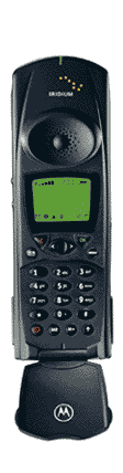
Figure 3 shows some of the Iridium capable devices available today. On the left is an Iridium only phone manufactured by Kyocera. In the middle is a dual mode phone produced by Motorola. It utilizes a GSM cassette to access Iridium and other GSM networks worldwide, and when in the range of a land based cellular network, it can convert for use as a regular cell phone. On the right are two Iridium capable pagers (top,Motorola; bottom,Kyocera). These provide the same functionality as regular pagers, with the added benefit of receiving pages anywhere in the world.
These phones are comparable in size and weight to some of the larger cellular phones on the market. The average weight of an Iridium handset is around 400 grams, and talk time of around 1-2 hours between charges.
Figure 3
Iridium uses several ranges of frequencies for communications between its transmitters, satellites, and ground stations. The service link between the phone and the satellite operates in the L-band. The L-band is between 1 and 2 GHz. The phone to satellite uplink in Iridium specifically takes place in the frequency range from 1616 MHz to 1626.5 MHz. Communication between satellites (cross links or intersatellite links) takes place in the Ka band of frequencies, between 23.18 GHz and 23.38 GHz. The Ka band is also used for communication between the satellites and the gateways. This link is called the feeder link, and for the Iridium system, the uplinks are in the frequency range 29.1-29.3 GHz. The downlinks, from the satellite to the gateway, are handled in the 19.4-19.6 GHz range.
The following is a chart showing frequency ranges and what frequencies some mobile services have allotted to them. The Iridium service link operates in part of the dashed portion of the graph on the left.
Figure 4
Since the Iridium system follows the GSM architecture, I will present the physical layer in terms of GSM parameters. GSM is rapidly becoming the worldwide standard for digital mobile communications, and along with several derivatives, such as PCS 1900 and DCS 1800, it is steadily replacing the analog Advanced Mobile Phone Service (AMPS) protocol.
The propagation delay for any satellite system will be relatively high, but in the case of Iridium, it is much lower than most systems. Iridium benefits from a low earth orbit, therefore the transfer or propagation delay will be significantly less than GEO (geostationary orbit) or MEO (medium Earth orbit) systems, whose orbits can easily extend past 10,000 miles. Using c, the speed of light, equal to 299,792,458 meters per second and an altitude of 420 miles (780 km), the propagation delay for Iridium equals 2.6 milliseconds. This is low when considering the fact that this is the propagation delay for a satellite system. It is because of this delay that satellites are primarily limited by propagation delay, but in the case of Iridium, delay plays less of a role. For example, in a GEO system with an altitude of 50,000 km, the propagation delay would be 167 milliseconds. In terms of voice communications, this delay in addition to the delays from encoding, modulation, multiplexing, and decoding would seriously hamper real-time communications. The low propagation delay of Iridium makes it ideal for voice communications.
It is important in the context of this report not to confuse propagation delay with transmission delay. Propagation delay is the time it takes for a signal to travel from the transmitter to the satellite. Transmission delay is the total time necessary for the signal to be sent from the user to the receiving party. This includes the propagation time to and from the satellite, and time spent encoding, modulating, multiplexing, and any time spent at the gateway. If the receiving party is connected to the PSTN, the time spent connecting to and routing through the PSTN is also added to the transmission delay.
Power is an important issue to discuss. In the Iridium system, the power required to transmit from the phone to the satellite is small since in a LEO system the propagation distance is small when considering other satellite networks. LEO satellites are classified as having an orbital altitude of less than 1000 miles. Since the Iridium satellites are about 420 miles away, the power required to transmit is small, and the transmitter required to produce such power can easily fit into a cellular type phone, although the Iridium units are slightly larger than their current terrestrial counterparts. The phones on the market today produce about .645W of power, which is sufficient to transmit to the nearest satellite.
The channel capacity for Iridium voice is currently only 2.4 kbps. The channel capacity for data and facsimile transmission over Iridium is 2400 baud. The gross bit rate for this system is much higher than 2400 kbps, but encoding, transmission delay, and other factors such as error detecion reduce the channel capacity greatly. The real improvement in channel capacity will come with the advent of the proposed Iridium Next Generation. The details haven't been confirmed yet, but the system will include 96 satellites and use Macro cell technology. Proposed channel capacity is expected to reach 384 kbps with Iridium Next Generation.
Since the iridium system uses GSM technology, the multiplexing techniques it utilizes are a combination of frequency division multiple access (FDMA) and time division multiple access (TDMA). The function of a satellite is as a radio frequency repeater. A satellite receives a signal on a certain frequency, then modulates it to another frequency and sends it to the next node in the network, which could be a ground station that sends it back to another satellite to repeat the process. The Iridium network is no exception. A signal is sent from a transmitter (phone) up to the satellite in the L-band range of frequencies. The satellite then assigns the signal to a certain traffic channel (TCH). The traffic channel assignment consists of a new frequency (determined through FDMA), and an uplink and downlink time slot. The assignment of a time slot is as a result of a TDMA process. Now the user has a physical channel assigned over which data can be transferred. The actual frame creation will be discussed in full detail in the Frame Structure section under Data Link Layer Attributes.
The Iridium system uses quaternary phase shift keying (QPSK) to modulate the digital signal for transmission on the analog carrier frequency. Quaternary, or quadrature phase shift keying is a form of phase modulation (PM) that uses 4 different phase angles for modulation. The angles are usually out of phase by 90 degrees. Signal modulation is one area where Iridium differs from the GSM standards. GSM uses uses Gaussian-filtered Minimum Shift Keying, where the modulation scheme is based on the gaussian distribution.
In order for information to flow reliably, the data must be arranged into a certain frame format. The GSM TDMA frame consists of 8 burst periods which last approximately 0.577 milliseconds each. Each individual physical channel is defined as a one of the eight burst periods per TDMA frame. Each traffic channel consists of 26 TDMA frames grouped together to form a 26 frame-multiframe. The duration of the 26 frame-multiframe is 120 milliseconds, which is calculated by multiplying the duration of the burst period by 8 to equal the time for one TDMA frame, and then multiplying that result by 26. The following figure shows the frame format and content.
Figure 5
As can be seen in the above figure, 24 frames of the 26-frame multiframe are used for traffic (frames 0-11 and frames 13-24). Frame 12 is used for the common channel. The common channel contains administrative data that can be accessed by all users. In this case, frame 12 contains the slow associated control channel (SACCH). The control channel can be used for several purposes. For example, frame 12 can be used as a paging channel (PCH) to notify the user that they have an incoming call. The following table shows the various common channels and their function.
Broadcast Control Channel (BCCH) Broadcasts station identity, frequency allocations, frequency-hopping sequences Freq. Correction Channel (FCCH) and Synchronization Channel (SCH) Synchronizes the user to a time slot Random Access Channel (RACH) Requests access to the network using Slotted Aloha Paging Channel (PCH) Alerts user to an incoming call Access Grant Channel (AGCH) Allocates a stand-alone dedicated control channel to the user after a request on the RACH The normal burst outlined in figure 5 above is used to transfer data and signaling and is one of four types of bursts used in GSM and Iridium.The other types of bursts include the F burst and the S burst which are used on the frequency correction channel and synchronization channel respectively. The fourth type of burst is the access burst which is used in the random access channel. The F and S bursts have lengths identical to the normal burst. The access burst is shorter than the other three since is is only used by the user to request access to the network.
The structure of the normal burst includes 3 tail bits at the beginning and end of the data (similar to start-of-header and end-of-header), 2 data blocks of 57 bits each, 1 stealing bit per data block, and a guard sequence at the end of the burst. The 26 bit training sequence is used for equalization. This training sequence is necessary because it helps to filter out the unwanted signal reflections that occur in wireless transmissions, leaving only the original signal. This also helps reduce the effects of multipath fading.
Another characteristic of this system that reduces multipath fading is the use of slow frequency hopping. In slow frequency hopping, each TDMA frame is transmitted on a different carrier frequency. The algorithm used to define frequency hopping is transmitted on the Broadcast Control Channel (BCCH).
One factor of GSM I found interesting was the use of discontinuous transmission. Not only does discontinuous transmission (DTX) reduce co-channel interference, it also conserves power in the transmitter. It does this by using Voice Activity Detection to turn off the transmitter when a voice signal is not detected. And instead of total silence at the receiving end, it creates what is called comfort noise at the receiver, which is accomplished by matching the background noise of the transmitter.
Error detection and correction is achieved in GSM type architecture through the use convolutional encoding and block interleaving. The speech codec that is used to encode speech into data is similar to the encoding process used to compress and decompress data into WAV and AIFF files. For every 20 millisecond voice sample, a 260 bit block is produced by the codec. The first 50 bits are referred to as Class Ia, which are most sensitive to bit errors. The next 132 bits are Class Ib bits, and are moderately sensitive to bit errors. The last 78 bits make up Class II bits, which are the least sensitive to bit errors. Since Class Ia bits are the most sensitive to bit errors, a 3 bit Cyclic Redundancy Code is added to these bits. The Class Ia and Class Ib bits are then fed into a half rate convolutional encoder. This encoder produces 2 output bits per input bit as a result of combining the previous 4 input bits. This adds considerable overhead to the sample, which in turn reduces the channel capacity of the system. Block interleaving is simply splitting the output bits of the encoder into 57 bit chunks that can then be transmitted in the normal burst frame. Having the sample split up in for transfer helps reduce the effect that burst errors have on voice transmission.
As mentioned previously, call routing, although handled by the satellites, requires routing tables from the gateways. The gateways create routing tables that are updated with current system useage, such as which users are in calls and which are in idle mode. These routing tables are continually broadcast up to the satellites because the electronics necessary to create these tables are complex and would increase the cost of each satellite. Low per satellite cost was one main factor in producing the Iridium system, and their relative simplicity allows them to be produced in a matter of weeks, not months.
CONCLUSION
It remains to be seen if Iridium will catch on with the average business and personal mobile phone user. Currently, Iridium has only a few thousand customers, for the main reason of high phone prices (approximately $3000 per unit) and high per minute rates (around $2.00/minute). The technology is still new, so prices will come down, but the question is will the prices come down enough for the average user. With a new version of Iridium on the horizon, the channel rates will be increased to make Iridium a feasible option for data communications for inaccessible regions of the globe. For right now however, terrestrial based GSM will satisfy the requirements of most users.
http://www.mot.com/GSS/CSG/Satellite/index.html
http://www.kyocera.co.jp/frame/product/telecom/iridium-e/index_e.html
http://www.ee.surrey.ac.uk/Personal/L.Wood/constellations/iridium.html
http://www.gsmworld.com/satellite/index.htm
http://www.ee.mtu.edu/courses/ee465/groupl/
http://ccnga.uwaterloo.ca/~jscouria/trio.html
http://ntia.its.bldrdoc.gov/fs-1037/fs-1037c.htm
Figure 1 http://www.ee.surrey.ac.uk/Personal/L.Wood/constellations/iridium.html
Figure 2 http://www.ee.mtu.edu/courses/ee465/groupl/services.gif
Figure 3 http://www.iridium.com/english/prodserv/products/index.html
Figure 4 http://pcsdata.com/frequency.html