|
|

SPAEA |
|
|
|
SPAEA |
|
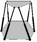
A Stewart Platform consists of six variable length links connecting a stationary base to a movable platform. The legs can be connected to the base and platform by either ball joints and/or universal (Hooke) joints (sometimes with an additional pivot). For the general Stewart Platform, the base and the platform can be any shape whatsoever as long as the resulting structure remains stable. For example, a structure with regular hexagons for both the base and the platform would result in an unstable configuration. By changing the lengths of the legs, the position and orientation of the platform can be changed with respect to the base, thus causing the relative motion of the platform. In order to understand the relationships of the general Stewart Platform, a kinematic model is needed.
The nominal model of the Stewart Platform is based on the following assumptions:
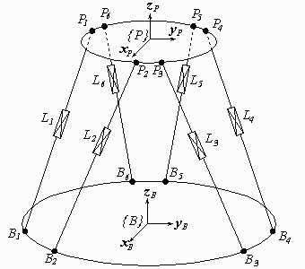
Figure 1 Nominal Model of a Stewart Platform and Figure 2 Vector Chain for Leg i will help illustrate some definitions. A base coordinate frame {B} is arbitrarily embedded in the base, and likewise a platform coordinate frame {P} is placed on the platform. Vectors referenced in coordinate frame {B} are denoted by Bv , while vectors referenced in {P} are denoted Pv. Additional coordinate frames may be used to describe relationships between the base frame and a world frame, or between the platform frame and the tool frame, but these other frames are omitted here for clarity and with no loss of generality.
 |
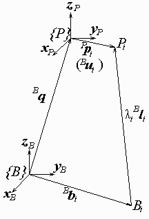 |
| Figure 1 Nominal Model of a Stewart Platform | Figure 2 Vector Chain for Leg i |
The joints on the base are denoted by Bi, i = 1,
2..6, and the position of the joint centers with respect to {B} are
given by the vectors 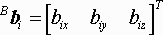 . Similarly, the joints on the platform are denoted by
Pi, and the position of the joint centers with respect to
{P} are given by vectors
. Similarly, the joints on the platform are denoted by
Pi, and the position of the joint centers with respect to
{P} are given by vectors  . The six legs are denoted by Li, with
vector from Bi to Pi defined by
. The six legs are denoted by Li, with
vector from Bi to Pi defined by  , where
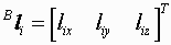 is the
magnitude (the length of the leg), and li is a direction unit
vector. Each leg has some sort of transducer that is able to read the length of
the leg, so that
is the
magnitude (the length of the leg), and li is a direction unit
vector. Each leg has some sort of transducer that is able to read the length of
the leg, so that  is a measurable quantity. A vector
  will be used to
describe the measured leg lengths.
will be used to
describe the measured leg lengths.
The two coordinate frames {B} and {P} can be related to each other through a displacement Bq=[x y z]T and an orientation matrix BRP.
 |
(1) |
|---|
The vector Bq gives the relative displacement of the
origin of {P} from the origin of {B} in terms of the its
longitudinal (x), lateral (y), and vertical (z) components.
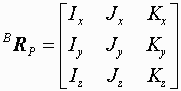
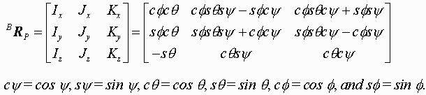
The orientation matrix BRP is composed of
direction cosines defined such that a unit vector along
xP has components (Ix Iy
Iz) in the base frame {B}. Similarly, a unit vector along
yP has components (Jx Jy
Jz) in {B}, and a unit vector along
zP has components (Kx Ky
Kz) in {B}. Of the nine variable in the orientation
matrix, six are redundant since only three values determine the orientation. Of
the many ways to describe orientation using three parameters, the most widely
used is the yaw-pitch-roll angles,  ,
,  , and
, and  (sometimes called a
Euler zyx rotation set). The orientation of frame {P} is obtained by
first rotating frame {B} an angle (roll) about the
z axis, then rotating the resulting frame an angle (pitch) about the
rolled y axis, and finally, rotating the resulting frame an angle
(yaw)
about the rolled and pitched x axis. The orientation of frame
{P} can be also described by the equivalent rotation set of first
rotating frame {B} an angle (yaw) about the
xB axis, then rotating the resulting frame an angle
(pitch) about the yB axis, and finally, rotating that
frame an angle (roll) about the zB axis (see Paul for a
further explanation). Thus, an orientation vector will be defined using the
yaw-pitch-roll angles as so that the orientation matrix is given by
(sometimes called a
Euler zyx rotation set). The orientation of frame {P} is obtained by
first rotating frame {B} an angle (roll) about the
z axis, then rotating the resulting frame an angle (pitch) about the
rolled y axis, and finally, rotating the resulting frame an angle
(yaw)
about the rolled and pitched x axis. The orientation of frame
{P} can be also described by the equivalent rotation set of first
rotating frame {B} an angle (yaw) about the
xB axis, then rotating the resulting frame an angle
(pitch) about the yB axis, and finally, rotating that
frame an angle (roll) about the zB axis (see Paul for a
further explanation). Thus, an orientation vector will be defined using the
yaw-pitch-roll angles as so that the orientation matrix is given by
 |
(2) |
|---|
The pose will be formalized by defining a pose vector P=[x y z ]. The pose vector thus defines
the position of the platform with respect to the platform [by its longitudinal
(x), lateral (y), and vertical (z) displacements], and its
orientation [by the yaw (), pitch (), and roll () angles].
For robust operation and control of a Stewart Platform, it is usually necessary to know both the pose of the platform P, and the lengths of the legs L.
The inverse kinematics problem of the Stewart Platform deals with calculating the leg lengths when the pose is given. In effect, it is a mapping from global pose to local actuator lengths, P to L. With the assumptions of the nominal model, the inverse kinematics of a Stewart Platform are uncomplicated, yielding a nonlinear closed form solution.
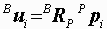
For convenience, let Bui be a representation of a vector from the origin of {P} to Pi, but referenced in the base frame so that
 |
(3) |
|---|
Then, following the vector chain in Figure 1 from {B} to {P} to Pi to Bi back to {B} yields
 |
(4) |
|---|
which rearranges to
 |
(5) |
|---|
The length of leg i can then be determined by taking the magnitude of Equation 5.
 |
(6) |
|---|
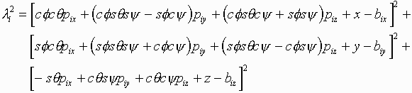
Expanding Equation 6 and squaring both sides for ease of reading gives
 |
(7) |
|---|
Equations 6 and 7 present the inverse kinematics for the nominal representation of a general Stewart Platform. By specifying the position and orientation of the platform, P, along with knowledge of the kinematic parameters, the leg lengths, L, can be calculated.
No Stewart Platform is a perfect situation generator. In fact, the position and motion of the tool will inevitably vary from nominal. Among the most likely phenomena to introduce errors in pose are the following [Liegeois]:
The direct relationship between these error sources and resulting pose errors is not well known. Therefore, the effects of the error sources are incorporated into error vectors that help create an accurate model of the Stewart. This model should shed light on the major contributors to pose inaccuracies and aid in future design and manufacture of Stewart Platforms.
A paper outlining the error model has been submitted to the CIRP. Until publication, however, the accurate model used in the software will not be presented here (please check back at mid March, if interested). Information on the accurate model can be obtained through email.
| Introduction | The Model | Software Testbed |
 Last revised 3/18/97 by Amit Patel.
Sugesstions, questions, or comments are
appreciated.
Last revised 3/18/97 by Amit Patel.
Sugesstions, questions, or comments are
appreciated.