|
Inductor-capacitor "tank" circuit
Inductor-capacitor "tank" circuit
PARTS AND MATERIALS
- Oscilloscope
- Assortment of non-polarized capacitors (0.1 µF to 10 µF)
- Step-down power transformer (120V / 6 V)
- 10 kΩ resistors
- Six-volt battery
The power transformer is used simply as an inductor, with only one
winding connected. The unused winding should be left open. A simple
iron core, single-winding inductor (sometimes known as a choke) may also be used, but such inductors are more difficult to obtain than power transformers.
CROSS-REFERENCES
Lessons In Electric Circuits, Volume 2, chapter 6: "Resonance"
LEARNING OBJECTIVES
- How to build a resonant circuit
- Effects of capacitor size on resonant frequency
- How to produce antiresonance
SCHEMATIC DIAGRAM
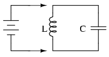
ILLUSTRATION
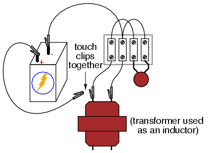
INSTRUCTIONS
If an inductor and a capacitor are connected in parallel with each
other, and then briefly energized by connection to a DC voltage source,
oscillations will ensue as energy is exchanged from the capacitor to
inductor and visa-versa. These oscillations may be viewed with an
oscilloscope connected in parallel with the inductor/capacitor circuit.
Parallel inductor/capacitor circuits are commonly known as tank circuits.
Important note: I recommend against using a PC/sound card
as an oscilloscope for this experiment, because very high voltages can
be generated by the inductor when the battery is disconnected
(inductive "kickback"). These high voltages will surely damage the
sound card's input, and perhaps other portions of the computer as well.
A tank circuit's natural frequency, called the resonant frequency, is determined by the size of the inductor and the size of the capacitor, according to the following equation:
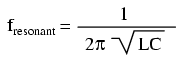
Many small power transformers have primary (120 volt) winding
inductances of approximately 1 H. Use this figure as a rough estimate
of inductance for your circuit to calculate expected oscillation
frequency.
Ideally, the oscillations produced by a tank circuit continue
indefinitely. Realistically, oscillations will decay in amplitude over
the course of several cycles due to the resistive and magnetic losses
of the inductor. Inductors with a high "Q" rating will, of course,
produce longer-lasting oscillations than low-Q inductors.
Try changing capacitor values and noting the effect on oscillation
frequency. You might notice changes in the duration of oscillations as
well, due to capacitor size. Since you know how to calculate resonant
frequency from inductance and capacitance, can you figure out a way to
calculate inductor inductance from known values of circuit capacitance
(as measured by a capacitance meter) and resonant frequency (as
measured by an oscilloscope)?
Resistance may be intentionally added to the circuit -- either in
series or parallel -- for the express purpose of dampening
oscillations. This effect of resistance dampening tank circuit
oscillation is known as antiresonance. It is analogous to the action of a shock absorber in dampening the bouncing of a car after striking a bump in the road.
COMPUTER SIMULATION
Schematic with SPICE node numbers:
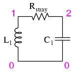
Rstray is placed in the circuit to dampen oscillations and produce a more realistic simulation. A lower Rstray
value causes longer-lived oscillations because less energy is
dissipated. Eliminating this resistor from the circuit results in
endless oscillation.
Netlist (make a text file containing the following text, verbatim):
tank circuit with loss
l1 1 0 1 ic=0
rstray 1 2 1000
c1 2 0 0.1u ic=6
.tran 0.1m 20m uic
.plot tran v(1,0)
.end
|