Ken Smith
Laboratory Scanner Lander
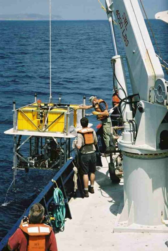
The scanner lander was developed as a platform to test our acoustic/optical sediment scanner at 4000 m depth. A notable feature of the lander is its four telescoping poles mounted on each corner of the lander frame and are intended to reduce sediment disturbance by slowing the lander’s descent rate just before contact. It was hoped that a soft landing would allow us to better evaluate the lander’s fluorometer. During launch, the poles extend below the lander about two meters and fill with water. Upon contacting the seafloor, the water is forced out through a small hole causing the lander to approach the sediment very slowly. The photo below shows the lander being recovered off San Diego during a shallow water test.

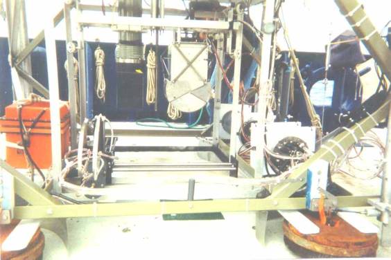
This photo shows the scanner lander mounted with the planar optode (green cylinder on left) and a stainless steel grab. A Deep Sea power and light Seabattery is on the left and the scanner controller and optode electronics cylinder is on the lower right. The scanner arm assembly is at its starting point next to the orange battery case. Stainless steel banding material is used to ferry the scanner motor and sensor cables between moving parts.

The photo below shows the scanner lander with two grabs, the scanner, and fluorometer housing (black cylinder on far lower rail). The circular weights (35 lb barbell plates) serve as footpads as well as ballast. The fluorometer housing is connected to a lens assembly (not visible) mounted on the scanning arm. Video of the scanner in operation at 4100 m depth shows a short clip of the Z-axis following the sediment surface.
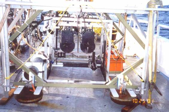

Table 1 shows the estimated power consumption of the proposed Rover II with scanner and benthic chamber systems. The table is based upon a seven month deployment with 50 measurement sites (3 d incubation per site and 1 d for transit between each site). A battery pack with 360 lithium D-cells is expected to provide ~1100 Ah battery capacity.
|
|
|
|
|
|
|
|
|
|
Component |
Operating |
Units |
Current/unit |
Time of
operation |
Sites unit
is |
Total time
of |
Total power |
|
|
Conditions |
|
@14V (amps) |
per site
(min) |
operational |
Operation
(hr) |
(amp-hr) |
|
Acoustic/Optical Scanner |
|
|
|
|
|
|
|
|
Controller |
1 op/site |
2 |
1 |
120 |
50 |
100.00 |
200.00 |
|
Drive motors |
1 op/site |
4 |
0.5 |
120 |
50 |
100.00 |
200.00 |
|
Fluorometer |
1op/site |
2 |
0.1 |
30 |
50 |
25.00 |
5.00 |
|
Benthic Chamber |
|
|
|
|
|
|
|
|
Stir motor |
continuous |
2 |
0.05 |
4320 |
50 |
3600.00 |
360.00 |
|
Purge valve |
1 op/site |
2 |
0.5 |
1 |
50 |
0.83 |
0.83 |
|
Chamber insertion motor |
2 op/site |
1 |
1 |
10 |
50 |
8.33 |
8.33 |
|
Planar optode |
1 op/site |
2 |
4 |
3 |
50 |
2.50 |
20.00 |
|
Central Controller |
continuous |
1 |
0.02 |
5760 |
50 |
4800.00 |
96.00 |
|
Current Meter |
continuous |
1 |
0.006 |
5760 |
50 |
4800.00 |
28.80 |
|
Video System |
|
|
|
|
|
0.00 |
0.00 |
|
Digital recorder |
1 op/site |
2 |
2 |
5 |
50 |
4.17 |
16.67 |
|
Camera |
1 op/site |
2 |
0.3 |
5 |
50 |
4.17 |
2.50 |
|
Flood lights |
1 op/site |
2 |
4 |
5 |
50 |
4.17 |
33.33 |
|
Propulsion Motor |
1 op/site |
2 |
7 |
2 |
50 |
1.67 |
23.33 |
|
Time Lapse Camera |
|
|
|
|
|
|
|
|
Digital camera |
28
frame/site |
1 |
1 |
10 |
50 |
8.33 |
8.33 |
|
Strobe |
28
frame/site |
1 |
1 |
5 |
50 |
4.17 |
4.17 |
|
Water Sampler |
1 op |
1 |
0.5 |
5 |
1 |
0.08 |
0.04 |
|
Acoustic Release |
self-powered |
2 |
|
|
|
|
|
|
ARGOS Transmitter |
self-powered |
1 |
|
|
|
|
|
|
|
|
|
|
|
|
|
|
|
Total Power
Requirement |
|
|
|
|
|
|
1007.34 |
|
|
|
|
|
|
|
|
|