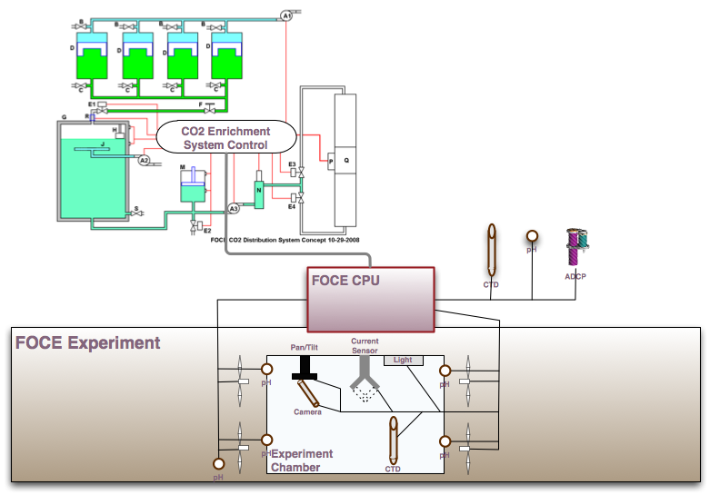
The planned FOCE operation involves two major subsystems, the FOCE Experiment and the CO2 Enrichment Subsystem (Figure 1). This document describes the two systems and their interactions, specifically identifying software interface capabilities that are required in each system.
This is an early draft of the document, meant to find a common agreement on the theory of operations and necessary interfaces. The components in Figure 1 are drawn based on best available documents, but may not reflect the most current design concepts.
Figure 1: FOCE Combined System Block Diagram
The FOCE Experiment is the system component that has been deployed to this point. It includes the entirety of the rack, controls, and sensors that are inside or mounted to the FOCE frame.
The chamber within the FOCE Experiment that is the area of primary study is called the Experiment Chamber.
The FOCE CPU is responsible for accessing all the sensors and retrieving their data, as well as controlling all the transducers. A SIAM instance runs on the FOCE CPU; the sensor data is collected via SIAM drivers, and stored on-board and relayed back to shore. The transducers are controlled (via SIAM drivers?), via commands emanating from shore.
The CO2 Enrichment System is the component responsible for creating enriched sea water using pure CO2 and in-situ sea water. It is being designed as a separate subsystem so that it can be used on other experiments and systems.
The controller for the CO2 Enrichment System is shown in the diagram as a part of that system. However, in the first version the controller may be implemented as part of the FOCE CPU. This unit will be referred to as the CO2ES Controller.
Two somewhat difference concepts have been mentioned for the operation of FOCE. They imply significantly different requirements on the CO2ES Controller commands and responses.
These are presented in the order they came to my attention, but the second, being from Bill Kirkwood, should perhaps be considered normative.
The FOCE Experiment concept of operations is straightforward at its first level. To create an environment with controlled pH but everything else as close as possible to the native conditions, the fans must be able to create sufficient flow to manage CO2 levels, and otherwise match external flow (by volume) as closely as possible. The default operational scenario for FOCE will therefore be:
At this point, the concept of operations will vary, depending on the concept for the CO2 Enrichment System operations, but control of pH may require further adjustments to the fan speeds. See the next 2 sections for more information.
There are other additional operational concepts that may be desirable for the FOCE fan operation, resulting in different modes for controlling the fans. In addition to the default operational scenario, users may want support for fixed flow rates; for flow rates that offset the in situ speed by a given amount; or for flow rates just like in the basic scenario above, but always matching ambient water speeds (as in 3.2), without regard to need for adequate pH level management. (The last will be necessary to verify that the FOCE installation is not affecting science results, and that always maintaining a minimum flow rate is not itself a cause of changes.)
In this concept, the level of enrichment and amount of flow from the CO2 Enrichment System can be controlled, the latter in real time and the former possibly in real time. Multiple feedback modes may be available within the CO2 Enrichment System:
So the sequence of operations, after initiating FOCE Experiment operations, is likely to be something like:
Under this scenario, epending on which method is chosen to change the pH, the FOCE Experiment may have to change its fan speed according to the pH and quantity of delivered sea water.
In this concept, the CO2 Enrichment System has two modes: On, and Off. When it is On, pH-enhanced sea water is being generated, and is flowing out of the system. It may be possible to vary the pH that is produced, but only by a small amount. Once turned on, the CO2 Enrichment System may not be turned off before the CO2 chambers are empty.
In this scenario, the sequence of operations after initiating FOCE Experiment operations is:
Obviously a much simpler concept, but at the same time a much less flexible one.
Note that in this model of operations, there may be a mismatch between the speed of production of enriched water, and the flow rate of water through the FOCE Experiment. Presumbably the diversion valve can be used in an analog fashion to keep these aligned, or possibly the pump speed for the sea water leaving the CO2ES can be controlled to make water outflow match water intake.
Under any concept of operations, the CO2ES Controller will have to be able to report information from all sensors within the CO2 Enrichment System. (See Appendix for list.) This is necessary to allow operators to perform failsafe and other basic system operations. The sensors to report will include:
Whether the controller reads CO2ES sensors in some direct way, or through a local SIAM instantiation, or as part of the FOCE Experiment CPU SIAM instantiation, is not yet defined (that I know of).
The externally available controls over the CO2 Enrichment System operations have not been defined. In one scenario, commands for many or all of the controlled components (see Appendix for list) will be externally available, and might be manually controlled some or all of the time.
In the other scenario, the system is internally driven, and only the most basic controls are available externally: Begin Enrichment, Divert Enriched Sea Water (so it doesn't go into the FOCE Experiment), and possibly a setting for Desired pH level. (Stop Enrichment is not needed in this scearnio because stopping the process would cause internal problems in the system.)
The path by which commands reach transducers is likewise not defined; it likely goes through the CO2ES Controller, which likely is running SIAM.
The functions already in the FOCE CPU will undoubtedly remain. The design question is whether to add the following to the CPU: CO2ES functions , and higher-level control loops to factor in the additional axes of control under the Complex Enrichment Control scenario above.
If the FOCE CPU accesses the sensor readings from the CO2ES by going through the CO2ES controller (a likely proposition), some interface must be defined or chosen for that communication.
On the other hand, if the CO2ES readouts are obtained independently, its controller software must support an interface for providing that information.
It may be desired that the FOCE CPU controls the CO2ES controller (for example, the servo loops and their settings), or any of its components. If it does so by talking to a separate controller (e.g., a standalone CO2 Enrichment System controller), some interface will have to be defined or chosen for that communication.
On the other hand, if the CO2ES devices are controlled independently, its controller software must support an interface for providing that information.
The following components of the CO2 Enrichment System appear to be sensors (indicated by > after), transducers (indicated by > before), or both. This list is taken from the "Notes from a FOCE Subgroup meeting regarding the design of the CO2 Distribution System. 10-29-2008"
Commands Input |
Component | Sensor Output |
> |
A1: CO2 Inlet Pump | ? |
> |
A2: Ambient Seawater Inlet Pump | ? |
> |
A3: CO2 Enriched Seawater Outlet Pump | > |
? |
B: Low Pressure Relief Valves | |
? |
C: High Pressure Relief Valves | |
> |
E: Electrically Actuated Ball Valves | |
> |
F: Manually Actuated Ball Valve | |
| H: Level Sensor with External Hall Sensors | > |
|
? |
J: Ambient Seawater Inlet Mixer | ? |
> |
K: CO2 Electronics Can (with Controller) | > |
| N: Inline pH Sensor | > |
|
> |
R: Heater (Electric?) | ? |