Custom Solution
Starting from a board and firmware (miniROV Light controller) that already checks many of the boxes, we can get a DAC with 16-bit resolution and only need some minor signal conditioning to drive the ±10V or even better directly drive the servos themselves. We also get the ability to ingest data and mirror it on registers from a sensor like the tilt sensor.
Bipolar +/-10V Analog Output from a Unipolar Voltage Output DAC
Image below taken from a TI app note
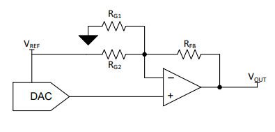
The transfer equation is:
\begin{equation} V_{OUT} = \left(1 + \frac{R_{FB}}{R_{G2}} + \frac{R_{FB}}{R_{G1}}\right)V_{DAC} - \frac{R_{FB}}{R_{G2}}V_{REF} \end{equation}Let $V_{REF} = 5$ and solve for the case when $V_{OUT} = -10$ and $V_{DAC} = 0$
We get the relationship:
\begin{equation} 2R_{G2} = R_{FB} \end{equation}Now let $V_{REF} = 5$ and solve for the case when $V_{OUT} = 10$ and $V_{DAC} = 5$
We get:
\begin{equation} R_{G1} = R_{FB} \end{equation}#Seed R_G2
R_G2 = 8.25e3
R_FB = 2*R_G2
R_G1 = R_FB
print(f'R_G1 = {R_G1:g}, R_G2 = {R_G2:g}, R_FB = {R_FB:g}')
So now our circuit looks like this:
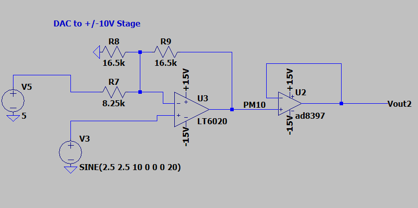
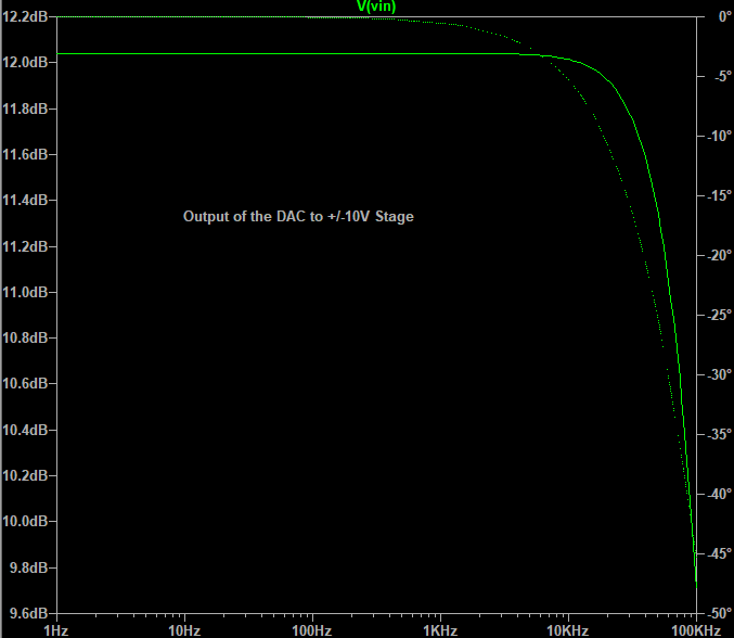
Using a LT6020 with a AD8397 unity gain buffer, we get the following bode plot for this stage:
Servo Drive using the Howland Current Pump
As laid out in this app notes from TI, AN-1515, and since the range of currents, despite the large inductances make this a conveinient and highly accurate solution if tuned properly.
For our solution, we will test feasibility again in SPICE, and see that a wide variety of 1-ampere, wide voltage op-amps can perform this task well. Our selection for test is again the AD8397. We can model the circuit below:
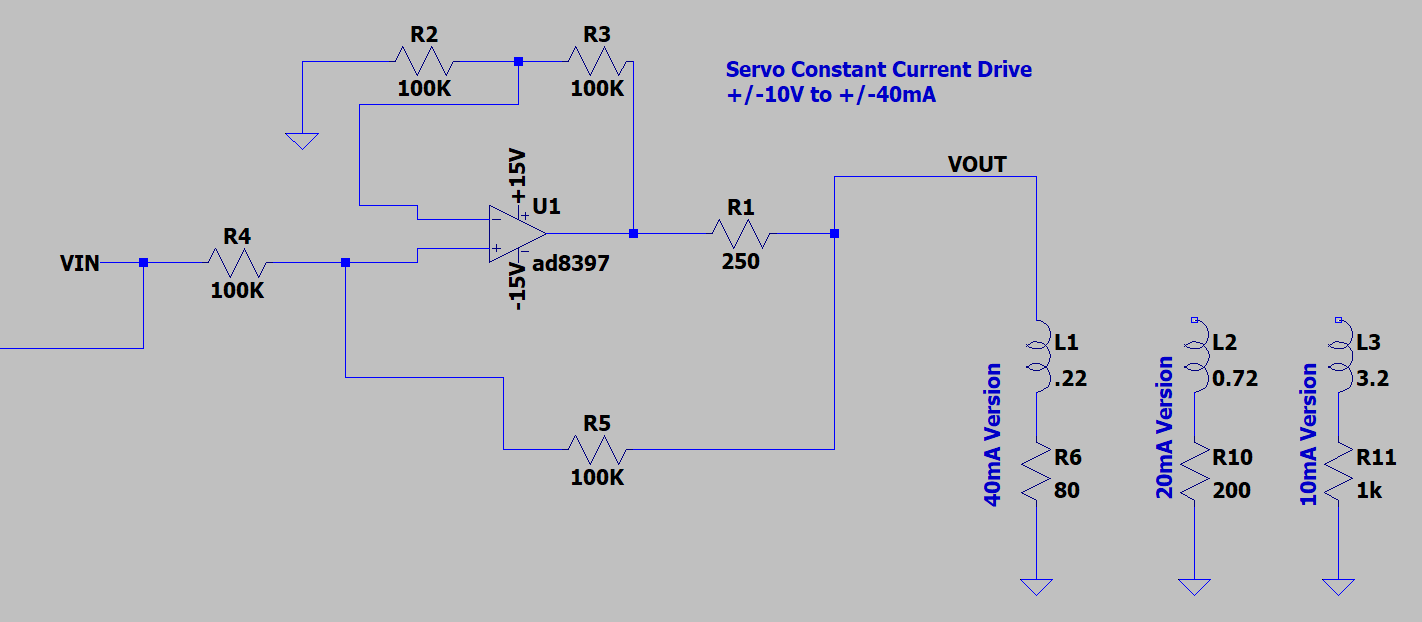
Which for the same AC analysis above provides the following response in current:
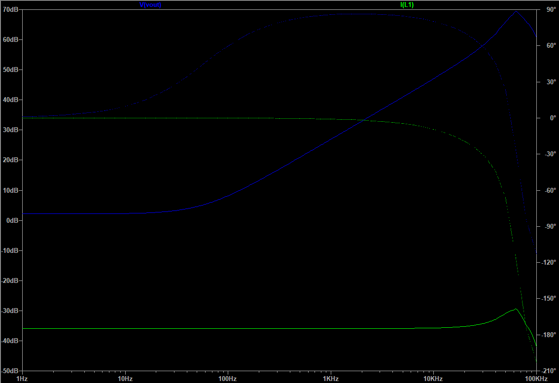
Here we can see that the circuit has the ability to modify voltage gain to keep the current output response flat, through 10kHz. Without belaboring the point, you can see we have the ability in this model to also test against the other coil options, a change to $R1$ will change the maximum output current, so future designs will have these range output control options.
import numpy as np
r_1 = lambda v,i:v/i
v_in = 10

coil_currents = np.array([0.040, 0.020, 0.010])
coil_resistances = np.array([80, 200, 1000])

for current in coil_currents:
    print(f' Coil Current: {current:g}-amperes => R1 = {r_1(v_in, current):,}-ohms')
DC/DC
To drive the amplifiers, we need DCDC that can source the following currents:
v_max = 15 #volts
i_max = v_max*coil_currents
print(f'Expected Maximum Watts for 2 channels is {2*np.max(i_max)}')
So, since most dual supplies are power rated for total watts in swing, we need $>2.4W$ supply
A good contender is the Recom REC-SRW Series of 3W converters, with 9-36V input and ±100mA outputs at 15V.