AutoSync dialog box
Use the AutoSync dialog box to set the accuracy of the vector line to rail fit, Z height values for the rails, allowed radius sizes, and G-code output that matches your machine control.
This function creates geometry to assist with multiaxis toolpaths and wirepaths on solid and surface models. Designed for parts where the upper and lower profiles (rails) need to be synchronized, Autosync Rails creates the rails at specific Z levels and adds proper branch lines to connect these profiles. By default, Autosync Rails selects all lines in your part as sync lines. Before you begin to create rails using this function, it is recommended that you move any existing lines in your part to another level and don't display that level while using the Autosync Rails function.
In the following example, where we used Autosync Rails to create upper and lower rails from a solid, you can see how the rails appear. In this example, the maximum Z height of the upper rail is set at a height above the top of the solid, and a minimum Z height of the lower rail at a height below the bottom of the solid.
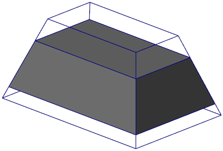
If you check Save Branch Lines and there are not the same number of endpoints created on both the top and bottom of the entity, the branch lines will not be created and projection to the trim planes will not occur. Slices are only created at the height of the upper and lower slicing planes.
 Parameters
Select
Return to the graphics window to select or reselect surfaces and/or solids on which to create the AutoSync rails.
Upper trim plane
Sets the projected Z plane height for the upper (UV) contour rail. Use Plane Select to return to the graphics window to select a point for the trim plane height.
Upper slice plane
Sets the Z plane height for the upper (UV) contour rail. Use Plane Select to return to the graphics window to select a point for the slice plane height.
Lower slice plane
Sets the Z plane height for the lower (XY) contour rail. Use Plane Select to return to the graphics window to select a point for the slice plane height.
Lower trim plane
Sets the projected Z plane height for the lower (XY) contour rail. Use Plane Select to return to the graphics window to select a point for the trim plane height.
Linear tolerance
Sets how closely the Autosync Rails vector lines fit along the upper and lower rails (the curve fitting tolerance to fit curves, line or arcs to the surfaces).
Level number
Sets the level on which the Autosync rails will be located. You can set the level in one of three ways:
- Select Use main level to keep the rails on the current level.
- Enter the number of a different level you want to assign in Level number.
- Choose Select to select a level using the Select Level dialog box.
Contour color
Shows the color number and a sample of the current color that will be used for the Autosync rails. To select a different color:
- Type its ID number in the Color parameter.
- Click Color to open the Colors dialog box and select or create a color.
Save branch lines
Check to save the branch lines when you connect the synchronized profiles. If this checkbox is checked and there is not the same number of endpoints created on both the top and bottom of the entity, the branch lines will not be created and projection to the trim planes will not occur. Slices are only created at the height of the upper and lower slicing planes.
Branch line color
Shows the color number and a sample of the current color that will be used for the branch lines. To select a different color:
- Type its ID number in the Color parameter.
- Click Color to open the Colors dialog box and select or create a color.


