Restmill Parameters tab
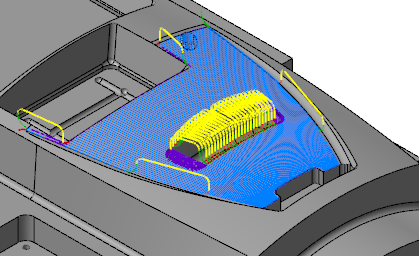
Use the Restmill Parameters tab to set the stepover, stepdown, transition motion, and other parameters for a Restmill toolpath. Restmill toolpaths are roughing operations that remove remaining stock based on a previous roughing toolpath (contour rough, contour finish, or pocket rough), or based on a roughing tool.
Motion control options include how the tool transitions between cuts, whether it uses climb or conventional milling, the amount of material to remove for each cut in Z (stepdown), and the amount to move the tool over in X and Y for each cut (stepover).
 Parameters
Total tolerance
Displays the sum of the Cut tolerance, the Line/arc tolerance, and Smoothing tolerance. Click Total tolerance to open the Arc Filter/Tolerance dialog box. Use the options in this dialog box to set parameters for filtering and smoothing toolpath motion within the specified total toolpath tolerance.
Maximum stepdown
Sets the distance between adjacent cuts in the Z axis.
Corner rounding radius
Enabled when Transition is set to High speed. Sets the radius of arcs generated when Mastercam encounters a sharp corner, defined as 135 degrees or less.
Stepover
Sets the distance between passes in the XY plane. If greater than 0, the toolpath uses multiple passes. If equal to 0, the toolpath uses only one pass.
Extension distance
Sets the distance which Mastercam extends both the beginning and the end of each cut. The extension can also minimize retracts and plunges because the distance can cause adjacent cuts to be joined.
Entry/exit arc/line
Select to turn on entry/exit arc or lines.
- Arc radius: Sets the size of the arc at the entry and exit points of a cut.
- Arc sweep: The value in degrees of the entry and exit arcs. For example, 180 would create a semicircular arc, 90 a quarter arc, and so on.
- Line length: Sets the length of the entry and exit lines.
- Allow arc/line outside boundary: Allows the entry/exit motion to extend beyond the tool containment boundary to allow for smoother motion and smoother surface finish.
Use approximate start point
Select to start the toolpath near the selected Approximate starting point from the Toolpath/surface selection dialog box. The toolpath uses the start point to set the starting side and stepover direction. When deselected, the toolpath starts toward the lower left of the machining plane.
Optimize cut order
Keeps the tool within an area until all cuts in that area are completed.
| Optimize cut order off | Optimize cut order on |
|---|---|
|

|
Minimize burial
When selected, the toolpath takes into account that the tool could be engaging material on both sides, as when machining between two bosses. To avoid this condition, additional retract and plunge moves may be generated. When deselected, the toolpath does not take into account that the tool could engage material on both sides.
Order cuts bottom to top
Performs the toolpath cuts starting at the bottom of the part and ending at the top of the part. Provides tool motion that moves up and out instead of in and down.
Direction of closed contour
Orients the cutting direction of the closed contours. Closed contours contain continuous motion without a need for a retract or reversal of direction. Select one of the following options:
- Climb: Cuts in one direction with the tool rotating in the opposite direction of the tool motion.
- Conventional: Cuts in one direction with the tool rotating in the same direction as the tool motion.
You can then set the Start length, which sets how far along the contour the toolpath begins. Each cut starts farther along by the amount of the start length. Eliminates dwell marks from forming in the same area of the part.
Direction of open contours
Orients the cutting direction of the open contours. Select one of the following options:
- One Way: Cuts the open contour by taking a pass, moving up to the retract height, moving back to the beginning of the cut, and taking another pass in the same direction. All passes are in the same direction.
- Zigzag: Cuts each pass in the opposite direction to the previous pass. A short linking motion connects the two ends.
Transition
Select one of the following the transition types:
- High speed: Inserts a loop between constant Z cuts if the transition between cuts is smaller than the loop length. Inserts a smooth move, often a spline, if the transition area is larger than the loop length.
- Broken: Moves the tool up and over, or over and down, between areas smaller than the gap size in the Gap settings dialog box.
- Ramp: Moves the tool at an angle in the Z axis from position to position between areas smaller than the gap size in the Gap settings dialog box.
- Follow surface: Tool Z motion matches the surface between areas smaller than the gap size in the Gap settings dialog box.
Loop length
Enabled when Transition is set to High speed. Determines the type of motion inserted between constant Z cuts in the toolpath. If the transition is larger than the specified length, a spline is inserted. If the transition is smaller than the specified length, the tool arcs off the part and helixes back on.
Ramp length
Enabled when Transition is set to High speed or Ramp. Sets the length of the ramp between the constant Z cuts of the toolpath. If set to 0 (zero), the selected transition motion is used in place of the ramp. The ramp is performed after any transition motion and after the exit arc, if selected.
Helix
Sets an entry helix for the plunge move onto the part. Click Helix to open the Helix parameters dialog box to enter parameters.
Cut depths
Sets the minimum and maximum depths either as absolute depths or relative to the top and bottom of the part. Additionally, sets depth cuts on flat surfaces and critical depths. Click Cut depths to open the Cut Depths dialog box.
Gap settings
Sets the handling of motion when there is a break in the tool motion, such as between two surfaces. Click Gap settings to open the Gap Settings dialog box.
Advanced settings
Sets tool roll motion at sharp corners between surfaces and at the extreme edges of the part, the corner tolerance, and performs checks on solid and surface models. Click Advanced settings to open the Advanced settings dialog box.


