Drafting panel
Use the Drafting function to create and format drafting dimensions or drafting notes and labels. You can modify the appearance of witness lines, add or remove leader lines, and edit the position, format, type, and alignment. Also, drafting entities are associated to the entity they are created on.
 What is the purpose of each page?
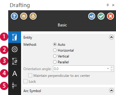
The Drafting function panel is made up of different pages.
-
Basic — Specifies the basics dimensions needed by the operations to build the entity. This includes the orientation and basic format.
-
Advanced — Defines the tolerances of the entity. The ability to alter the tolerances gives leeway to the measurement and how to orient the dimensions shown.
-
Dimension Attributes — Controls the format of the drafting entity. The dimension attributes include leading zeroes, trailing zeros, and symbols.
-
Dimension Text — Allows the change of the text including the direction, size, orientation, and dimensions.
-
Leaders/ Witness— Specifies the specifics of any leaders, witness lines and any arrows being used.
How do I edit
drafting dimensions?
Choose Smart Dimension from the Drafting tab. Click on the dimension to select it and make any changes in the Drafting function panel.
How do I change the orientation of a
dimension?
When you create a linear dimension, its orientation is initially defined with respect to the Cplane (as in horizontal or vertical dimensions) or the associated geometry (as in parallel, or tangent dimensions). Additionally, you can specify the orientation of a non-perpendicular, linear dimension by assigning it an Orientation angle. Enter a value between positive and negative 90 degrees (±90°). Entering a positive value rotates the dimension counterclockwise. Entering a negative value rotates the dimension clockwise.

- Orientation: Horizontal (0 deg)

- Orientation: -15 deg
To fix the orientation of a tangent dimension so that it is perpendicular to a line that connects the arc centers, use the Maintain perpendicular to arc center option .

- Tangent dimension
- Orientation: Perpendicular to arc centers
What is the
difference between witness lines and leader lines?
Witness lines are simple, straightforward drafting lines (no arrowheads) used to indicate boundaries or connect entities. In dimensions, witness lines are paired with parallel lines that indicate the end points of a dimension.
Leader lines are drafting lines with single arrowheads that function as pointers. In Mastercam, leader lines most often point from a dimension's text to its witness lines.
Can I dimension my part in multiple planes?
You can create dimensions in multiple planes without leaving the Drafting function. To do this, select a Cplane from the Status Bar at the bottom of the graphics window while dimensioning.
However, changing the construction plane only affects newly created dimensions. If you create a dimension in the Top plane and then select a new plane, the dimension is not updated. The Cplane you select remains active until you change it.
How do I regenerate
associated drafting entities?
You can use the Dimensions Settings property page in the System Configuration dialog box to specify regeneration parameters for the current session, as well as all subsequent sessions.
You can also use the Regeneration options located on the Drafting tab.
How do I use the on-screen trigger points to create tangent, circular, and conjugate angle dimensions?
When you dimension an arc or a circle, trigger points appear at each quadrant and are offset from the outside in 45-degree increments. Use these triggers to switch between creating a tangent dimension or circular dimension.
-
Hover over a quadrant trigger to create a tangent dimension, as shown in the image below.

-
Hover over an offset trigger to create a circular dimension, as shown in the image below.

When dimensioning an angle, eight trigger points display at each quadrant of the potential dimension. Hover over the trigger points to select the dimension to you want to create. The inner trigger then snaps your dimension to the lesser angle, while the outer trigger snaps it to the conjugate.


You can also use the Angular Sweep button on the Advanced tab to flip the direction of the angular dimension.
I really like how my modifications look. How can I save them to use again?
You can update your system defaults without opening the System Configuration dialog box or leaving the graphics window.
Click the Save Defaults button at the top of the panel to save your modifications to corresponding settings in the active system configuration file.

The next time you open the panel, whether or not it is the same Mastercam session, the panel defaults display your newly saved settings.
Help! I hate the formatting changes I made.
If you are not satisfied with your modifications, click the Load Defaults button to pull the system defaults back into the panel no matter how many changes you make.


