Panes: Machine Simulation
Machine Simulation provides various ways to analyze your simulation. By using the panes located on the View and Home tab, you can view the machine definition and progress of the current simulation, as well as apply color schemes to toolpaths to analyze changes.
 Move List
The Move List pane shows the NC code of the current simulation. The displayed values match the absolute machine coordinates, such as X, Y, and Z (in the case of 3-axis machining) and A, B, C, and so on in the case of 4- or 5-axis machining.
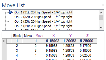
- Use the slider bar on the right side of the tab to scroll through the moves. Select a block to move the tool to that position.
- Overrun Axis Limits will display with an exclamation mark and collisions will display with an red cross
- Right-click the columns and select Settings to set the number of significant digits and to show text colors based on toolpath analysis options.
Analysis (Toolpath)
The Analysis pane applies color schemes on the toolpaths to analyze changes. Select one of the following drop-down options to apply these changes:
- Tool number: The toolpath will be different colors when different tools are being used.
- Operation number: Each toolpath is colored differently.
- Operation highlight: Colors the toolpaths based on the current operation.
- Sequence: The toolpath is colored to identify the start and end point of machining, as well as the cutting method.
- A/B Axis Value Scale: Colors the toolpath after the machine's rotation axis is tilted.
- A/B Axis Reversal: Colors the toolpath after the rotation axis is reversed.
- A/B Axis Value Change: Colors the toolpath when the tilt angle of the A, B, or C rotation axis values change.
- A/B Axis Speed: Colors the toolpath based on the start and end value (degree per inch) for the A or B axis.
- A + B Axis Speed: Colors the toolpath based on the combined A and B axis speed.
- Linear Axis Reversal: Colors the toolpath when the linear axis is reversed. A reversal can be defined by a threshold angle. The default threshold angle is 150 degrees.
- Orientation Change: Colors the toolpath after its orientation angle changes between two segments.
- Segment Length: Colors the toolpath based on the length of segments.
- Collisions and Proximity: Colors the toolpath based on its collisions status.
- Feed Rate: Colors the toolpath by machining feed rate and rapid moves.
- Height Change: Colors the toolpath when the tool changes its height relative to the toolpath.
- Axis Pole: Colors the toolpath to determine if the rotation axes are collinear.
- Single Marking: Colors all toolpaths to display in one single color.
Statistics
The Statistics pane displays information about the current operation. It is broken down into three sections.
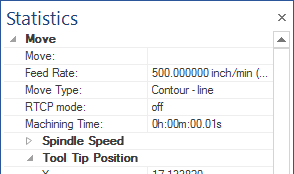
- The Move section displays information about the current position of the tool.
- The Operation section displays information about the current operation, such as its tool, the operation machining time, and feed rate time.
- The Sequence section displays information about the operation(s) in the current simulation, such as the number of operations, number of tool changes, and total machining time.
Machine
The Machine pane contains the machine definition of the current simulation. The display shows the hierarchical representation of the machine and how machine parts are defined.
You can save, create, or load an existing machine, view detailed element information, or activate machine editing from the options displayed at the top of the tab.
Below is an example of a machine shown in the tab:
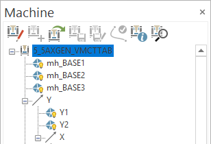
The icons shown in the Machine pane are described as follows:
| Icon | Description |
|---|---|

|
Translation axis |

|
Tool object |

|
Rotation axis |

|
Workpiece object |

|
Axis transformations |

|
Stock object |

|
Geometry objects |

|
Initial stock object |

|
Toolpath objects |

|
Collision definition sets |
Simulation
The Simulation pane is used set stop conditions during simulation.

You can set the following options:
- Pause simulation and notify on stop commands and conditions: Select to pause your simulation and notify you on your set stop commands and conditions.
- Stop on tool change: Select to have the simulation stop when changing the tool.
- Stop on operation change: Select to have the simulation stop on an operation change to a separate operation or for all operations.
- On Block: Select to have the simulation stop on the entered block value.
- On Bookmarks: Select to have the simulation stop on set bookmarks.
- Stop before occurrences: Select to have the simulation stop before the occurrences of tool change, operation change, or block change.
- Stop on new chip detection: Select to stop when a new chip has been detected.
- Stop at XYZ value: Select and enter X, Y, or Z values to stop the simulation at.
- Stop at XYZ value change: Select to stop the simulation when the X, Y, or Z values change.
Report
The Report pane is used to view all of the events that happen during simulation. Each operation and events are separated by their respective groups.
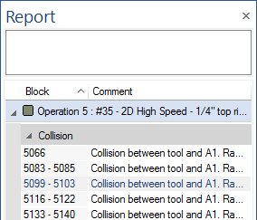
The type of events that are reported are:
- Value underflows
- Value overflows
- Collision events between axis geometry, such as a collision between the C-axis and the table
- Collision events between the tool and work piece
- Collision events between the stock and tool part
- Collision events between stock and the tool during rapid motions
You can customize the type of fields shown by right-clicking in the Report pane and selecting Field Chooser.
Click an operation or event to move the tool into that position in the toolpath.
Progress
The Progress pane displays the progress of the current simulation. This bar is on by default and located at the bottom of the Machine Simulation window.
Axis Control
The Axis Control pane is used to manually move the linear and rotational axes of the machine. Use the sliders to move the axes, or right-click in the Axis Control pane to set the values or set them all to zero.
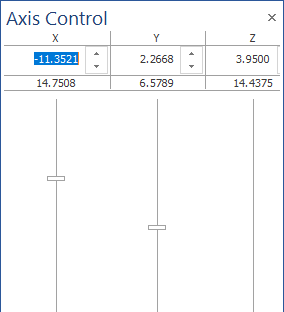
This is useful when checking if the machine limits or collision checking has been set correctly.
CutSim
The CutSim pane is used to make changes to your stock model.
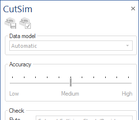
You can set the following options:
- Data Model: Set the data model to be Automatic, 3-axis model for 3 axis machining, or 5-axis to allow for undercut material removal.
- Accuracy: Use the slider bar to set the accuracy of the stock model resolution. Lowering the accuracy allows it to calculate faster, but you have a less accurate result. Raising the accuracy slows down the calculations, but the stock model is accurate.
- Check: Set whether the part of a tool should remove the material, should be collision checked, remove material and collision check, or do nothing.
You can also use the Save stock button at the top of the pane to save out the resulting stock model.
Analysis
The Analysis pane is used to apply color schemes on the rest material to analyze changes in the toolpath. Select one of the following drop-down options to apply these changes:
- Tool number: The material will be marked with different colors when different tools are being used.
- Operation number: The material is colored differently for each toolpath.
- Deviation: Colors the material offset compared to the target geometry. The color will change the more or less material exists on top of the target geometry.
- Height change: Colors the material to indicate whether a tool is plunging or cutting in and from material.
- Orientation change: Colors the material after the machines rotation axis changes the orientation.
- Toolpath length: Colors the material to indicate the length of the toolpath segments.
- Mark Parts: Colors chips which have been separated from the main part.
- Single Marking: Colors the rest material to display in one single color.
- Gouge Excess: Colors the material to indicate if it will gouge or not.
Measure
Use the Measure pane to measure different features of the stock, by using the drop-down options shown below:
- Points: Use this option to gather information on specific points in the current X, Y, and Z coordinates. [Ctrl+Middle mouse click] an area on the stock to display a small text box that indicates the Position, Deviation, Tool number, Move number, and Target ID.
- Distances: Use this option to measure the 3D distance between two points on the stock model. A text box will then display with the distance.
- Refine box: Use this option to zoom into a certain area of the stock model. The material around the refine box will be removed and leaves the selected area of stock.
- Remove chips: Use this option to select chips to keep, only keep one part, or set to automatic and only define parts.
Layer Interval Settings
Use the Layer Interval Settings pane to set options for the Layer Interval option (located on the Simulation tab). Layer Interval displays toolpaths only between two layers. You can set the following options:
- Layer Thickness (mm): Sets the layer thickness to Manual or Automatic. Only Manual is available at this time.
- Show Single Layer (based on Layer Thickness): Shows the toolpath motion on a single layer. Use the slider to change the current layer.
- Show Layer Range: Shows toolpath motion only between the upper and lower layers.
- Upper Layer: Sets the location of the upper layer.
- Show Section Plane: Displays the upper layer in the graphics window. Change the layer's color with the Color button.
- Lower Layer: Sets the location of the lower layer.
- Show Section Pane: Displays the lower layer in the graphics window. Change the layer's color with the Color button.
Reset
Located on the View tab. Resets the view to the default, which will remove all panes currently being displayed.


