Simulating Toolpaths
Mastercam provides several ways to preview your toolpath, helping you to spot errors in the program before machining your part. Use the drop-downs below to learn more about simulation.
 NCI and IOF
Standard (non-Mill-Turn) operations in Mastercam are represented by NCI code, an intermediate form of the g-code that your machine's post outputs. Mill-Turn operations, on the other hand, are represented by IOF code, the type of instructions that Sync Manager outputs. Mastercam Simulator uses these different types of intermediate code to run a simulation.
For example, when you run Mastercam Simulator on Mill operations, the simulation is based on the NCI file that Mastercam generates. If you run Mastercam Simulator on operations inside of Sync Manager, the simulation is run on the IOF file that Sync Manager generates. In fact, only operations simulated from within Sync Manager are based on IOF code.
Classic Backplot
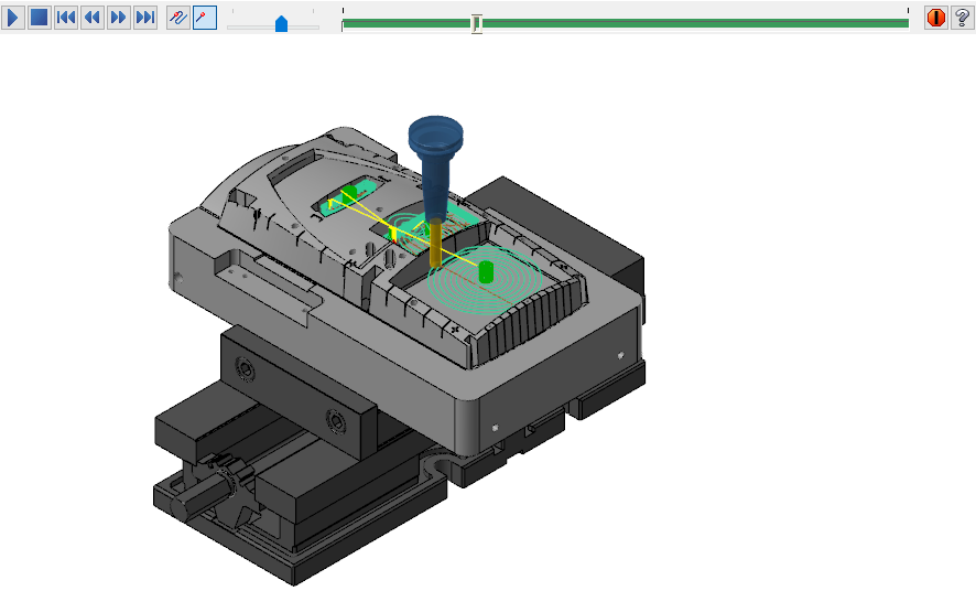
Classic Backplot lets you view tool motion without removing material.
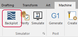
To use Classic Backplot select Backplot selected operations from the Toolpaths Manager or select Backplot from the Machine tab.

For more information about Classic Backplot refer to the following Help topics:
Mastercam Simulator
You can simulate and prove out your 3-axis, 4-axis, or 5-axis Mill, Mill-Turn, or Router toolpaths by using Mastercam Simulator in simulation mode. Simulating toolpaths helps you detect collisions between your stock, tools, and machine components before sending code to your machine tool.
Mastercam Simulator offers three ways to review tool motion:
- Backplot: Backplotting shows the path the tools take to cut your part. This display lets you spot errors in the program before you machine the part. As you move through the backplot, information about the current toolpath motion displays in the Move List. To use Mastercam Simulator to backplot a toolpath, select Verify selected operations from the Toolpaths Manager or Verify from the Machine tab. Then click Backplot in Mastercam Simulator's tab.
- Verify: Verifying your toolpaths allows you to use solid models to simulate part machining against a stock model. The verification result represents the surface finish, and shows collisions, if any exist. To use Mastercam Simulator to verify a toolpath, use the Verify selected operations button or drop-down from the Toolpaths Manager or Verify from the Machine tab.
- Simulation: View tool motion with material removal and a full machine model. This lets you check collisions and axis interactions. This mode is based on the stand-alone Machine Simulation; however, not all Machine Simulation functions are available within Mastercam Simulator.

Using Mastercam Simulator with Mill or Router
-
In Mastercam, select Simulation under Properties in the Toolpaths Manager.
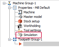
- Select the machine configuration from the Machine drop-down list. This list may vary if you have added machines to Mastercam.
- Set the Position, Post settings, and Arc curve tolerance if necessary.
- Click OK to save your changes and exit the dialog box.
-
Select Verify selected operations on the Toolpaths Manager.

Mastercam Simulator displays.
- On the Home tab, select Simulation.
- Select the Simulation contextual tab.
- Select Run to view your toolpaths, with the machine.
You can also use the Verify selected operations drop-down to choose Add to current verification.

There are restrictions when adding an operation to a current session.
-
Only operations positioned below the selected operations in the Toolpaths Manager can be added to the current session.
-
Operations that depend on a previous operation cannot be added unless the parent operation is also selected.
Inside Mastercam Simulator, hover over any of the functions to learn more about them.
Using Mastercam Simulator with Mill-Turn
- Create your toolpaths in Mastercam.
- Click the Post selected operations button.
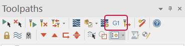
Mastercam opens Sync Manager.
- Create any required syncs and set Sync Manager options.
- Click the Launch button in the Sync Manager.
Machine Simulation
Machine Simulation is an effective way of proving out Mill or Router toolpaths. Machine Simulation helps you detect collisions between your stock, tools, and machine components.
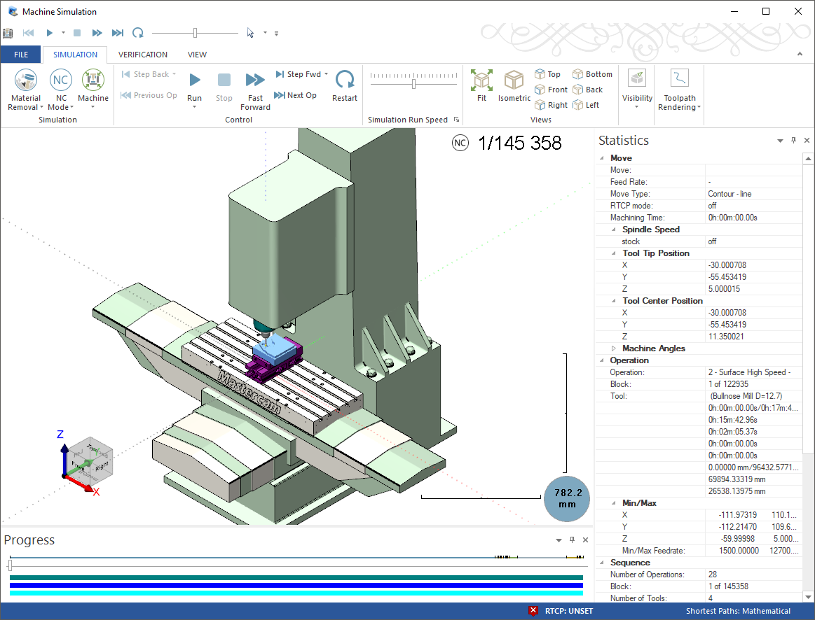
To use Machine Simulation select Run on the Machine tab. Before starting Machine Simulation, set options for the simulation in the Machine Simulation dialog box by selecting the dialog box launcher in the Machine Simulation group.
For more information about Machine Simulation, refer to the Working with Machine Simulation Help topic.
You can use Advanced Display (on the View tab) when running Classic Backplot or Mastercam Simulator. Advanced Display toggles the display of toolpaths with different colors, based on the move type.
Using reflection in Simulator
While setting up your simulation, use the Material texture option to improve simulations by applying reflective qualities to Milling, Stock, and Workpiece objects. This feature is only available in the Simulate mode of the Mastercam Simulator. This requires a material image to be added to the machine directory for the selected machine.
To activate this option:
-
Select the File menu, and choose Options from the Backstage menu.
-
Click the Graphics tab.
-
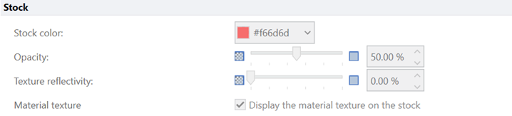
In the Milling, Stock, and Workpiece sections, select the Material texture option in each section to display the reflections in the simulation window.


-
Control the intensity of reflection by entering a Texture reflectivity value. You can also use the slider to adjust this value. The image below shows 100% reflectivity.

When adding your chosen metal .png file, you can choose any reflective metal image, color, or texture. Using a reflective material image in the machine directory is necessary to activate this feature. To do this, go to your machine simulation directory by following the file path in the image below.

Once in the MachSim folder, you can select any machine and drop your .png file in.
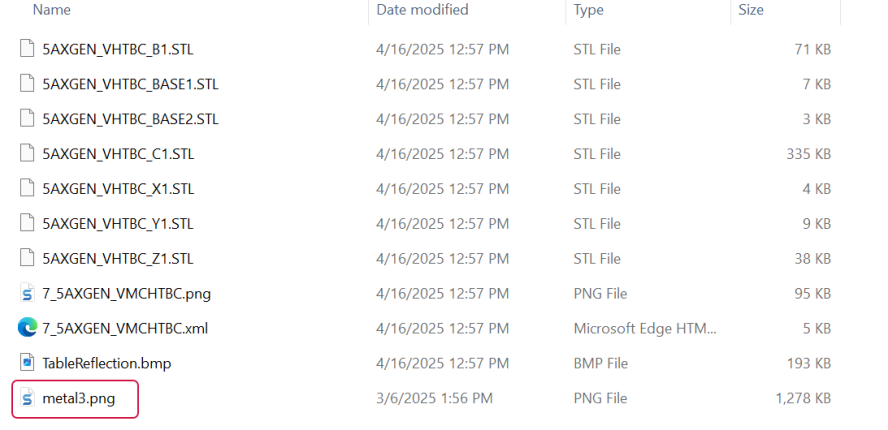
You can enable the reflectivity feature in the Backstage menu of Mastercam.


