Rectangular Pattern panel
Use Rectangular Pattern to create an array of solid bodies or features. You can create the copies as bosses or cuts. You specify the number of copies, a distance, an angle, and one or two directions.
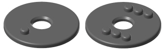
Each operation has three components:
- A target body. This is the solid model upon which the copied features will be applied.
- One or more tool bodies. These are the solid features or operations that will be copied.
- One or more results. These are the copies of the solid features that have been created.
Mastercam prompts you to select the target body as soon as you enter the function. If only one solid exists, Mastercam automatically selects it as the target.
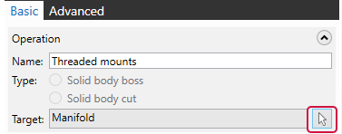
- Edit the default Name as desired. This is the label that will be used for this operation in the Solids Manager.
- The Target field lists the name of the solid that has been selected. Click the highlighted button to select a different target solid, if desired.
- If the feature that you are copying is a separate solid body from the target, you can choose Solid body boss to add the shape to the target body, or Solid body cut to remove it. If the selected feature is part of the target body, these options will be disabled.
After you select the target, Mastercam asks you to select one or more features on the model that you would like to copy. Select one or several features, and click End Selection to return to the function panel.
- You can select entities from the graphics window, or features from the Solids Manager.
- Your selection at this time is not final; you can select additional features, or remove them, from within the function panel.
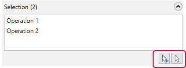
Mastercam lists the selected features or operations in the Selection window. Right-click in the window or use the highlighted buttons to add new features to the list, remove them, or clear the list completely. Click on an item to see it highlighted in the graphics window.
 Defining the locations of the copies
Use the Direction 1 settings to create a line of copies.
- Specify the number of copies that you want to create in the Instances field.
- Enter the desired Distance between them.
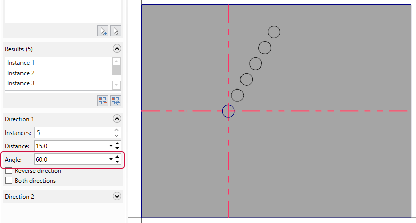
- Specify the Angle of the line relative to the X+ axis, which is zero.
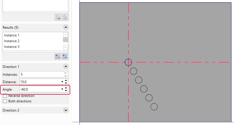
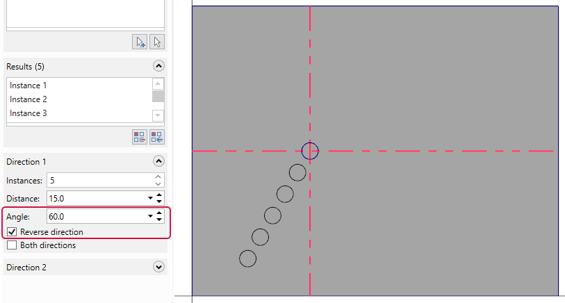
A positive Angle value rotates the line in the counter-clockwise direction, when seen from the top. A negative Angle value rotates the line in the clockwise direction. Select the Reverse direction option to flip the line 180 degrees. The following pictures show the difference between these options.
This picture shows five copies of the center hole being created at a 60-degree angle.
This picture shows what happens if you change the angle to –60 degrees.
This picture shows what happens if you select Reverse direction.
Use the Direction 2 settings to create copies of the row that is created by the Direction 1 settings, resulting in a two-dimensional array.
Mastercam lists each copy in the Results window. Click on an Instance to see it highlighted in the graphics window. Click the left button to remove it, or the right button to restore all of the copies.
Using Advanced options
By default, Mastercam updates the graphics window as you make changes to the list of items in the Selection and Results windows. You can turn off this behavior by deselecting Automatically preview results. When this option is turned off, click the Preview button to update the graphics window.
Also by default, Mastercam creates an entry in the Solids Manager for the operation. You can prevent this by selecting Do not create model history. However, if you select this option, all of the solid history will be removed, not just the entry for this operation.


