Power Surface
Use Power Surface to create surfaces by best fitting a surface through a series of curves and/or points. This function can be used to patch or fill holes, blend surfaces, or optimize surfaces. Besides surfaces, you can also use this function to create sheet solids or meshes.
When using this function, surfaces are controlled by a number of control points, weights, connectivity, and tangencies. Then, the surfaces are trimmed to the outside or inside curves. Neighboring surfaces may also be used as controls for connectivity and tangent continuity. Power Surface is capable of handling multiple combinations of constraints while each constraint can contain a combination of continuity behaviors; for example, position or surface normal direction for tangent continuity.
 Why am I getting a branch point error?
If you get an error stating that the selected sub-chain does not touch the base point, you need to increase the Chaining tolerance to select the chains you want to generate the surface from.
Chaining tolerance is on the Chaining Options dialog box, accessed through the Chaining dialog box.

How can I modify my surface results?
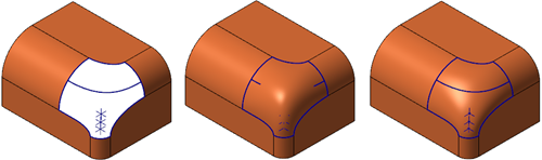
In some cases, to achieve a better result, you may need to create additional construction geometry. This additional geometry helps Power Surface correctly construct the surface.
In the example shown below, you can see how adding additional geometry helps to create the missing surface. Without adding the extra geometry to define the surface, the results do not accurately match the existing part and contain sharp transitions on the radius.
What are the different Use normal options and how do they affect my surface?
The Use normal option controls how the surface is shaped. Choose one of the following from the drop-down:
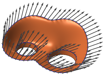
The Display vectors option (on the Advanced tab) is selected in the following images. This helps to show the flow of the created surfaces.
-
None: Sets the surface normal to the default.

-
Surface: Uses the surface normal vectors of surrounding surfaces.

-
Plane of chain: Uses the plane of each curve to determine the surface normal.

-
Cplane: Sets the surface normal to the active construction plane (Cplane).

-
X-axis, Y-axis, or Z-axis projection: Sets the normal to the X, Y, or Z axis. Y-axis projection is shown below.
-
Origin projection: Directs the normal towards the origin of the sphere when creating a spherical shape.

-
Surface and Cplane: Uses both the surface and Cplane normal vectors to construct surfaces.

How does adjusting UV control points affect my surface?
The UV control points option sets the number of points in the U and V grid to control the smoothness of the surface. Typically, a more complex surface requires a higher number of control points. However, using a high number of UV control points increases the file size.
To help determine the ideal UV control point definition, select the Extend surface option and deselect the Trim outer and Trim inner options. By doing so, you are provided with a better view of how the constructed surface behaves by observing the surface shape as it extends beyond the boundary curves and points.
| UV control points at 48 x 48 | UV control points at 10 x 10 |
|---|---|

|

|


