Misc page
Use the Misc page to control miscellaneous settings for your Multiaxis toolpath. This includes tip compensation, blade area roughing, and mirroring your toolpath.
 Parameters
Common toolpath dialog box controls
Parameters
Common toolpath dialog box controls
| Icon | Name | Description |
|---|---|---|

|
Detect (FBM Drill) | Analyzes the solid model and detects features based on the Feature Based Machining (FBM) operation's current parameters. View the results of all detected features and their machining information in the Features page. For more information, please refer to Detection States and Modes in FBM. |

|
Reselection is not available |
Hole Wizard features for a Wizard Holes operation can only be selected in Mastercam for SOLIDWORKS. Contact Mastercam for more information. NOTE
Mastercam for SOLIDWORKS is no longer supported starting with Mastercam 2024. |

|
Preview toolpath operations (FBM Drill/Wizard Holes) | Opens the Toolpath Operations Preview dialog box where you can view the list of operations FBM will generate using the current Features page list. |

|
Select default formulae file (3D high speed toolpaths) | Lets you select a different *.formula file, which Mastercam uses to calculate default values. |

|
Save parameters to defaults file | Makes the current toolpath settings the default for future toolpaths of this type. Saves the current values in the toolpath properties pages to the .mcam-defaults file specified in the machine group properties. |

|
Reload parameters from defaults file | Overwrites the current values in the toolpath properties pages with the toolpath's default parameters. These parameters are reloaded from the .mcam-defaults file specified in the machine group properties. |

|
Display graphical elements | Enables the display of graphical elements, such as plane labels and geometry colors. In 2D or 3D toolpaths Mastercam also has Display only elements on current page, Display plane labels, and Simplify plane display as options. |

|
Hide dialog | Minimizes the dialog box so that you can use other Mastercam functions, like changing your shading settings or the graphics window view. When finished, press [Esc] to maximize the dialog box. |

|
Tool Manager | Opens the Tool Manager. Use the Tool Manager to create and edit tool definitions and to work with tool libraries. When you close the Tool Manager, the toolpath dialog box will reappear just as you left it. |

|
Feed speed calculator | Opens the Feed & Speed Calculator dialog box where you can modify the calculated feed rate or spindle speed by adjusting the material and tool parameters. |
|
None |
Page window | This window displays all of the pages that are available to you, depending on the selected toolpath type. A green check mark indicates pages where data has changed in the current session. |
| None | Quick View Settings | This window summarizes key toolpath information from the Tool page, Coolant page, and Planes page. It updates automatically as you make changes to the different pages and is always visible. |
| None | Generate toolpath | When selected, automatically generates the toolpath when you click OK. For more information, refer to Accepting and Generating Toolpaths. |

|
OK | Generates the toolpath and closes the dialog box. If editing a toolpath, applies the changes and closes the dialog box. |

|
Apply | Applies your changes to the toolpath without closing the dialog box. |

|
Cancel | Closes the dialog box and cancels the toolpath creation. If editing a toolpath, any changes to the toolpath are discarded. |
Not all options are available for all toolpaths.
Tip compensation
Select whether the compensation point will be the center of the tool or the tip. Compensating to the center of the tool is frequently used with ball cutters where compensation is applied at the control.
Blade Area Roughing
Blade area roughing
Select to enable the Blade area roughing parameters.
Calculation applied
Select one of the following options for when the calculation will be applied:
- Before tilting: Morphs the toolpath between the impeller blades before performing collision checks on the blade swarfing motion.
- After collision control: Morphs the toolpath between the impeller blades after performing collision checks on the blade swarfing motion.
Rotary axis around
Use the drop-down menu to select the axis to rotate about.
Rotary axis base point
Returns you to the graphics window to select the base point for the rotary axis.
Maximum stepover
Enter a value for the maximum distance between cutting passes.
Number of cuts per section
Enter the number of cuts to make between a pair of blades.
Cutting method
Selecting a cutting method from the drop-down list:
- One way (along rotary axis): Starts at upper edge of impeller floor, ends at lower edge, retracts and moves to upper edge for next cut.
- One way (along revolution rotary axis): Starts at lower edge of impeller floor, ends at upper edge, retracts and moves to lower edge for next cut.
- Zig zag: Starts at one edge of the impeller floor, cuts to the opposite end, steps over, cuts to the first edge, etc. Cuts are created from left to right between the impeller blades.
- Zig zag (climb only): Starts at one edge of the impeller floor, cuts to the opposite end, steps over, cuts to the first edge, etc. Cuts are created from the center of the floor surface between the impeller blades and expand outward.
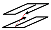
Alternate direction to reduce path length
Select to have the toolpath alternate directions as show below. Available only when Number of cuts per section and Zig zag (climb only) are both selected.
Area
Select an option from the drop-down list:
- Complete: Entire area between two blades.
- Left side: Area between the left blade and the splitter blade.
- Right side: Area between the right blade and the splitter blade.
Trim cuts
Select to enable trim cuts. Choose one of the following options:
- By percentage of cut length: Select and enter a percentage by which to shorten the cuts. The actual distance is calculated as the percentage of the current cut's length.
- When curvature exceeds tool diameter: Select to trim the cut in areas such as at the upper radius of the blade.
Extension
Enter a distance to extend the toolpath at the start or at the end of a cut.
Depth cuts
Select to enable depth cuts. Enter the following:
- Number: Enter the number of depth cuts to create. The number of cuts should be sufficient to remove all material between the impeller floor and the shroud surrounding the impeller.
- Spacing: Enter the distance along the tool axis to be used between cuts.
- Start height: Enter a height above the impeller floor along the tool axis to begin the calculation of depth cuts.
Smoothing above splitter
Select to create a morphed toolpath in the area above the splitter blade. This finishing strategy provides a smoother path along the impeller floor when a splitter blade interrupts the normal flow of the toolpath.
Miscellaneous
Maximum angle step for rotations axis
Sets the maximum tool angle change for axis rotations.
Set Y axis machine limits
Enter the lower and upper Y axis limits for your machine. This option is left unselected unless you have a need to limit the Y axis within a specific range.
- Lower: The lower Y-axis machine limit.
- Upper: The upper Y-axis machine limit.
Smooth surface normals
Enter a value for the smoothing threshold in the activated field.
Calculation based on tool center
Select to use the tool center for toolpath calculation. The tool pivots around the tool center rather than the contact point with the surface. The result is a toolpath with different tool axis vectors and position coordinates.
Mirroring
Plane normal
Replicates the toolpath motion about an axis or a selected Line. If you choose Line, use the Select button to return to the graphics window to select one or more lines as the plane normal.
Plane base point
Returns you to the graphics window to select a point to define the mirror plane's base point.
Toolpath copy
Keeps both the original and mirrored toolpath motion. When deselected, only the mirrored toolpath motion remains.
Selecting this option does not create a new toolpath operation in the Toolpaths Manager. All motion is tied to the original toolpath.


