Set Up Your Print
To start printing successfully, take time to learn and use PreForm software to setup each model and ensure a successful print.
You’ve set up your printer, filled the resin tank, and installed PreForm Software. You're ready to start printing! Make sure your printer is plugged into a power outlet and connected to your computer with a USB cable.
Learn to Use PreForm
PreForm’s interface is simple and easy to use. Learn the controls and best ways to interact with the print preparation software in our tutorial series.
Open PreForm Software
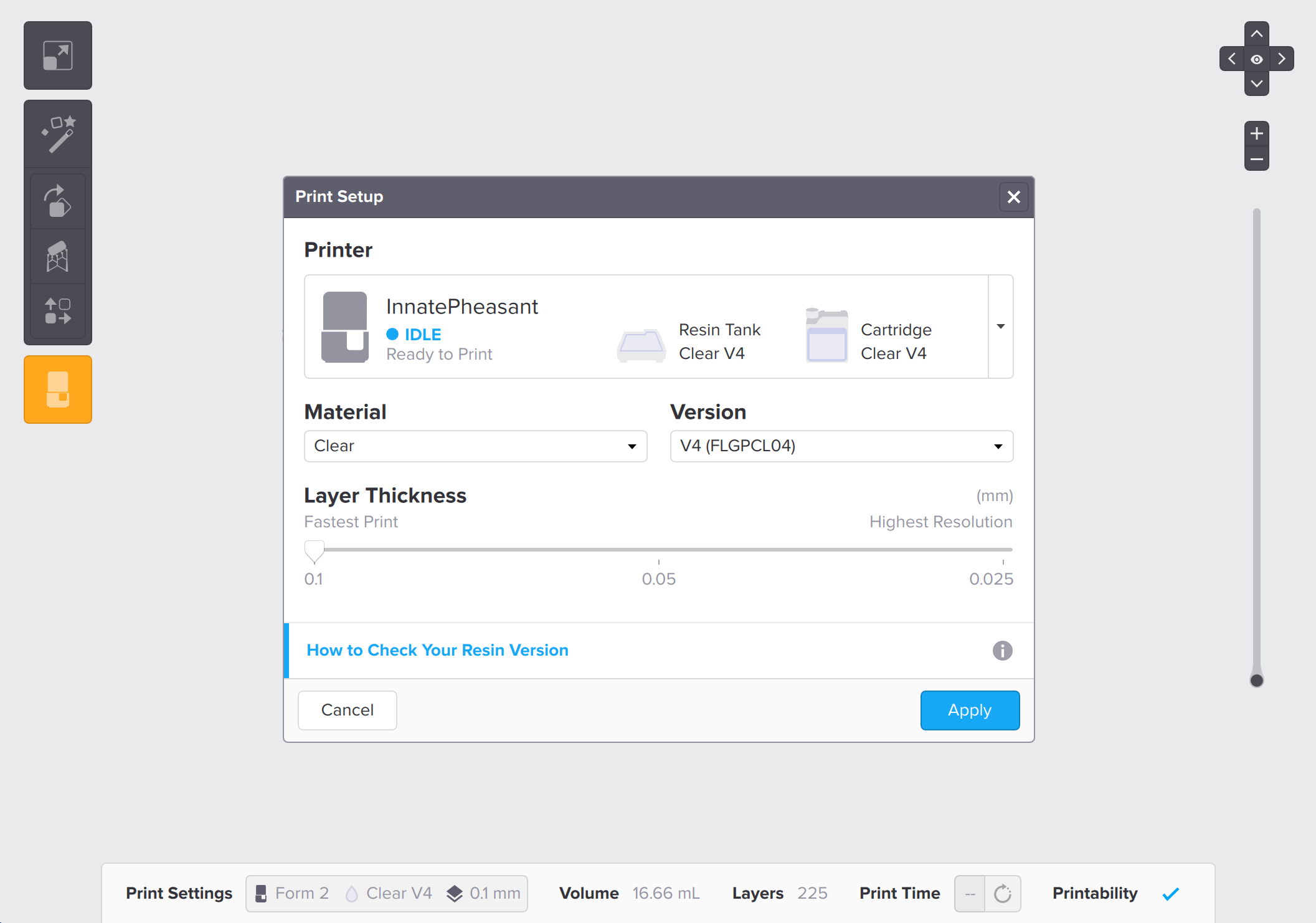
The Print Setup window opens when PreForm launches. Use the material selection drop-down menus to select the material type and version for the specific print job.
TIP:
Select "Current Printer Settings" in the Material drop-down menu to apply the material settings last used on the printer.Use the slider to select the layer thickness for the print, likely 0.05 mm or 0.1 mm. Reserve 0.025 mm for rare occasions that require incredibly high resolution. Change the layer thickness setting later by clicking “Print Settings” on the bottom bar.
Formlabs Account Login
Log in to PreForm with a Formlabs account to link print jobs to the account and to enable Dashboard notifications for only prints linked to the account. The linked account name also appears on the Form 2 for print jobs uploaded onto the printer while logged in.
TIP
Log in to help track individual prints and manage shared printers more easily.
Click the “Log In” button on the “Print Settings” toolbar at the bottom of the window or on the “Print” menu to open the Formlabs account login window. Log in to an existing Formlabs account, create a new account, or retrieve a password. Log out to unlink the print job from an account.
Load a Model
PreForm Software supports STL and OBJ files, which you can export from most 3D CAD or animation packages. To load a model, drag and drop it into Preform or select “Open” from the File menu.
One-Click Print
Select the One-Click Print option to automatically orient, support, and layout each part. After sequentially completing all three print setup steps, PreForm opens the Print dialog window to confirm and send the job to a printer, so ensure that you've connected and selected the appropriate printer type, material type, and layer height before beginning One-Click Print. The specific printer can be selected by serial name from the Print dialog.
Change the View
Viewing your model from the correct angle can help you position things in just the right way. PreForm offers a couple of ways to control your view.
The View Menu
Hover over the View icon to reveal the view controls. The center icon will always take you to the initial view. The other icons rotate your view 90 degrees to the top, sides, or bottom. You can use the plus and minus buttons to zoom in and out.
TIP
Right click and drag will rotate the view about the model. Right mouse and shift will pan. Use the scroll wheel to zoom in and out.
Mouse and Keyboard Controls
Control PreForm using the mouse and keyboard. Type '?' at any time in PreForm to view a list of keyboard shortcuts. Learning these keys will make part set-up fast and easy.
PreForm can also be controlled using third-party SpaceMouse hardware. PreForm automatically detects the SpaceMouse if the mouse device is connected when PreForm opens. Use the SpaceMouse to rotate, zoom, or pan the camera view. The first button on the SpaceMouse will reset the camera view, similarly to typing ‘F’ on the keyboard or selecting View > Home in the menu bar.
Model List
Use the Model List to find and select individual models in the scene by model name.
To show or to hide the Model List, select or deselect “Show Model List” under the “View” menu.
To turn on or to turn off the visibility of a model in the print scene, select or deselect the model in the Model List. Only the models visible in the scene will print.
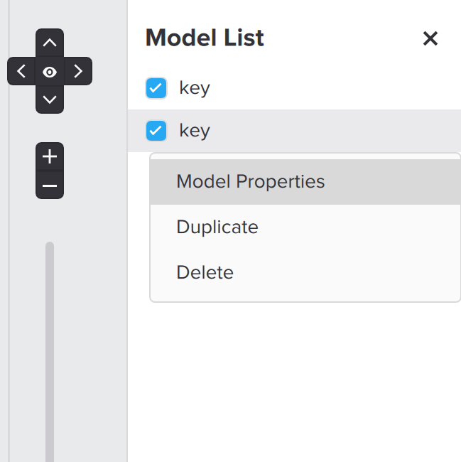
Right-click any model in the Model List to do the following:
- View model properties and change the model name
- Duplicate the model in the scene
- Delete the model from the scene
Model Properties
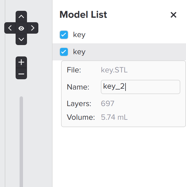
To view the model properties or to change the model name, right-click any model in the print scene or in the Model List and select “Model Properties”.
“Model Properties” displays the following information:
- File: This field displays the file name of the original OBJ or STL file.
- Name: This field displays the model name, which is also used for the Raft Label. To change the model name, click the "Name" box to modify the text. Press Enter/Return or click outside the menu to save the new model name. Updating the model name also updates the Raft Label.
- Layers: This field displays the number of layers in the printed part.
- Volume: This field displays the estimated resin consumption for the printed part.
Inspect Models with the Slicer Tool
Before uploading models for printing, use the Slicer tool to inspect models for any internal model errors or model features that may affect printability, such as minima, cups, and undersupported areas.
The Slicer tool is a vertical slider located on the right side of the PreForm screen below the View menu. Use the mouse or keyboard shortcuts to move the slider up and down to inspect individual layers of the model and support structures. To view a list of keyboard shortcuts, type '?' in PreForm.
When the Slicer tool is in use, a box with the layer number appears on the left of the slider. Click the box to edit and type a layer number to direct the Slicer tool to a specific layer.
Toolbar Menu
Select a model by clicking on it. The model will turn blue and display the overlaid manipulator sphere with three circular axes to indicate that the model is selected. Once a model is selected, use PreForm Software features to manipulate the object.
TIP
To toggle the visibility of the overlaid manipulator, select “View > Show/Hide Manipulators” from the PreForm menu.
Size or Scale
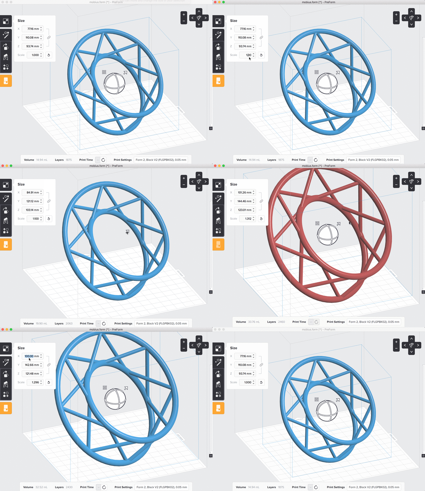
Before generating supports, set the size of each model. Use the left toolbar to input size values, or click and drag the arrow in the top-right of the manipulator that is overlaid on the model. Click the “Size” icon or press the “S” key resize the model from the toolbar. Options for adjusting the size of a print in PreForm:
- Direct resizing: when any model is selected, click on the the arrow - above and to the right of the sphere - and drag to resize the model.
- Scale factor: change the size of your model by entering a specific factor from the Size toolbar.
- Nominal dimensions: type a specific value into any axis in the Size toolbar to resize the model, with all axes' dimensions adjusting respective to the input value.
- Units: toggle between millimeters and inches from the PreForm Edit menu. Configure the unit settings when exporting the file from the modeling program, before importing into PreForm.
Orient
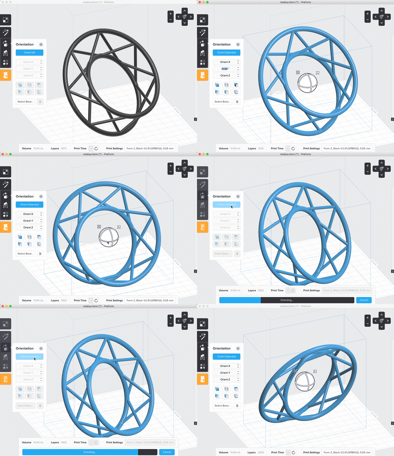
Models’ orientation can be adjusted throughout the print set-up process. Note that changing the X or Y orientation will require regenerating supports. You can use the overlaid spherical manipulator, no matter what tool you have selected on the toolbar to the left of the screen. However, clicking on the “Orientation” (shortcut O) icon in the toolbar will give you additional options for adjusting the model’s orientation. The tools available for adjusting orientation in PreForm are as follows:
- Drag rotation: click to select a model, then click and drag the spherical manipulator to rotate the model freely. Select one of the circular rings to rotate the file about a singular axis.
- From the left toolbar:
- Orient Selected: PreForm will compute an optimal orientation for printing.
- Plane-orientation: flip your model along each axis with the shaded cube icons.
- Axis orientation: rotate your model precisely by typing specific angles for each axis.
- Select Base: select a face to point toward the build platform.
TIP
Model orientation can greatly affect the success of your print. Prepare your model in an orientation that is best suited for print quality on the axis you care about most. We recommend trying auto-orient for optimal results.
Layout or Translate
Configure prints across the build platform before sending the job to print. Use the toolbar, or move any model by clicking and dragging a selected part. Click the “Layout” icon or press the “L” key to reorient your view so that you look down on the build platform from above. From any tool, move the model around by clicking and dragging the four-directional arrow or any part of the model outside of the sphere. Choosing “Layout All” or “Layout Selected” will allow PreForm to recommend a layout for the current file set.
Duplicate
While in Layout mode, you can make one or more copies of the selected model by using the Duplicates feature. You can print as many models as will fit on the build platform. You can also use other PreForm features above to set a different size or alignment in the build area for each copy.
Import Other Models
Your printer can print multiple models at once, whether duplicates or different models. Import additional models the same way you imported the first model. Remove a model from the build area by simply selecting it and pressing delete or backspace on your keyboard.
Generate Supports
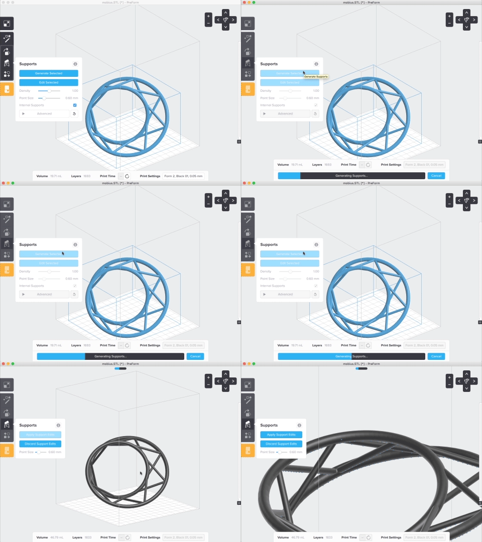
Almost all models need support structures for a successful print, especially those with overhangs. Learn more about what supports do for your model. Click the “Supports” icon or press the “C” key to access support structure features:
- Generate Selected: generate supports using the current settings for a selected model.
- Generate All: generate supports for all models in your scene.
- Advanced: configure custom settings for flat spacing, raft thickness, slope factor, and height above raft
TIP
For trickier parts, it can take time to find the perfect orientation with optimal support settings. Use manual supports to selectively add and remove supports after auto-generating.
Printability
When a model is loaded into PreForm, algorithms analyze the model geometry and detect areas that may affect the printability, or the likelihood of a successful print.
PreForm highlights three types of part features that reduce printability: minima, cups, and undersupported areas.
PreForm runs a printability check for minima and cups before and after generating supports. PreForm checks for undersupported areas only after supports have generated.
Minima
A minimum point—plural: minima—refers to the lowest local point in any area of a model’s geometry relative to the build platform. Unsupported minima may break off the part during printing and lead to structural defects, warping, or print failures, all of which can contaminate resin, damage the resin tank, or cause resin spills. Learn more about identifying minima in “Chapter 6: Local Minima and Islands” from the video tutorial "Supporting Your Model in PreForm".
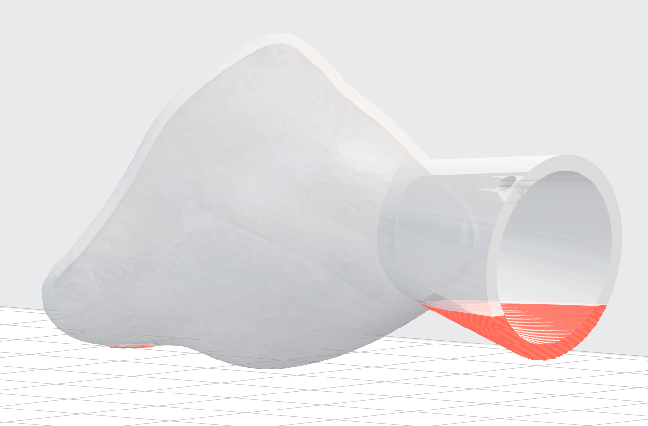
Minima are highlighted in red and will fail without additional support. Resolve unsupported minima on models using one of the following methods in PreForm:
- Add at least one touchpoint to the lowest part of the highlighted area using the Supports tool.
- Rotate the highlighted areas away from the build platform using the Orientation tool.
To switch the printability display for minima in PreForm, use the keyboard shortcut Alt+1 on Windows and Option+1 on macOS, or on the PreForm menu bar, click View > Printability Display, and select or deselect “Show Minima”.
Cups
“Cups” refer to hollow volumes or cavities in a model. Hollow volumes and concave geometries require more careful attention to the print orientation. When the opening of a cup faces the resin tank, the cup traps air and resin as the build platform lowers the opening of the cup against the bottom of the resin tank. The resulting suction can cause separation between printed layers, structural defects, warping, and print failures, all of which can contaminate resin, damage the resin tank, or cause resin spills.
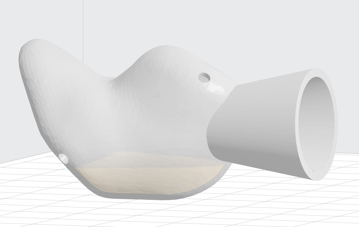
Cups that reduce printability are highlighted in orange. To resolve highlighted cups, re-orient the model using the Orientation tool so that the opening of the cavity either faces the build platform or is rotated at an angle, and then regenerate supports.
Learn more about identifying and orienting cups in “Chapter 4: Orienting Cupped Areas” from the video tutorial "Orienting Your Model for Printing".
TIP
For models that contain internal hollows or are enclosed volumes (for example, a hollow sphere), use CAD software to either fill in the hollow or add drainage holes in the hollow to minimize suction effects during printing and to avoid trapping resin inside the part.
To switch the printability display for cups in PreForm, use the keyboard shortcut Alt+2 on Windows and Option+2 on macOS, or on the PreForm menu bar, click View > Printability Display and select or deselect “Show Cups”.
Undersupported Areas
“Undersupported areas” refers to areas that may require additional supports to print successfully. Undersupported areas are frequently overhangs (also known as “islands”), or features that would print without being attached to a raft or another layer.
Undersupported areas are highlighted with a red gradient. The intensity of the red indicates the overall impact on printability. A deeper red indicates a print failure is likely while a lighter red indicates possible structural defects or warping.
Resolve undersupported areas on models using one of the following methods in PreForm:
- Add additional support touchpoints to the highlighted area using the Supports tool.
- Rotate the highlighted areas away from the build platform using the Orientation tool to reduce overhangs.
Learn more about undersupported areas.
Print the Scene
Upload a Print Job
With the printer connected to PreForm, click the orange printer button in the left toolbar to access the “Print” menu.
On the “Print” menu, select the appropriate printer by serial name, choose a name for the print job, and assign an account name for the job. Click “Log In” to set the account name from a Formlabs account. The job name and account name both appear on the jobs list on the touchscreen display once the job uploads to the printer.
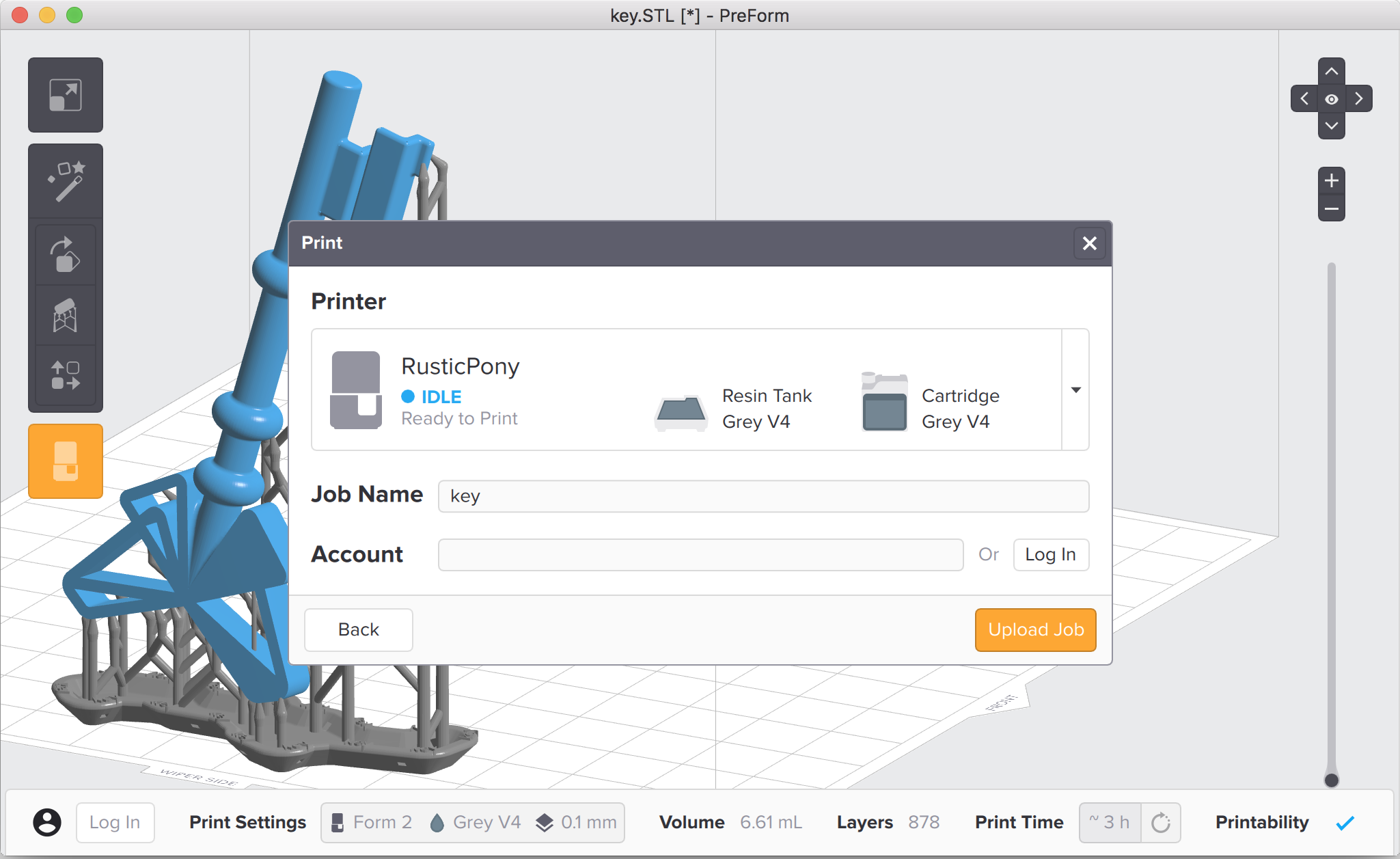
Log in to an existing Formlabs account to link print jobs to the account and to enable Dashboard notifications for only prints linked to the account. Log out to unlink the print job from an account.
Pay attention to any pre-print reminders or warnings. Ensure the correct resin tank and cartridge are installed.
Click “Upload Job” to send the print job to the printer.
NOTE
For a Form 1+, click “Upload Job” once the resin tank is clean and the resin tank is filled with resin.
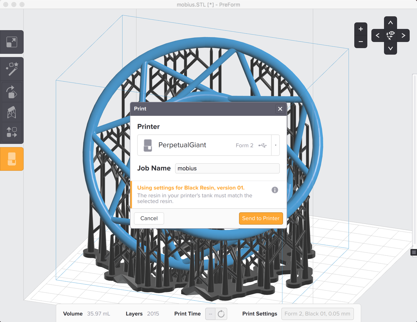
Complete the File Transfer
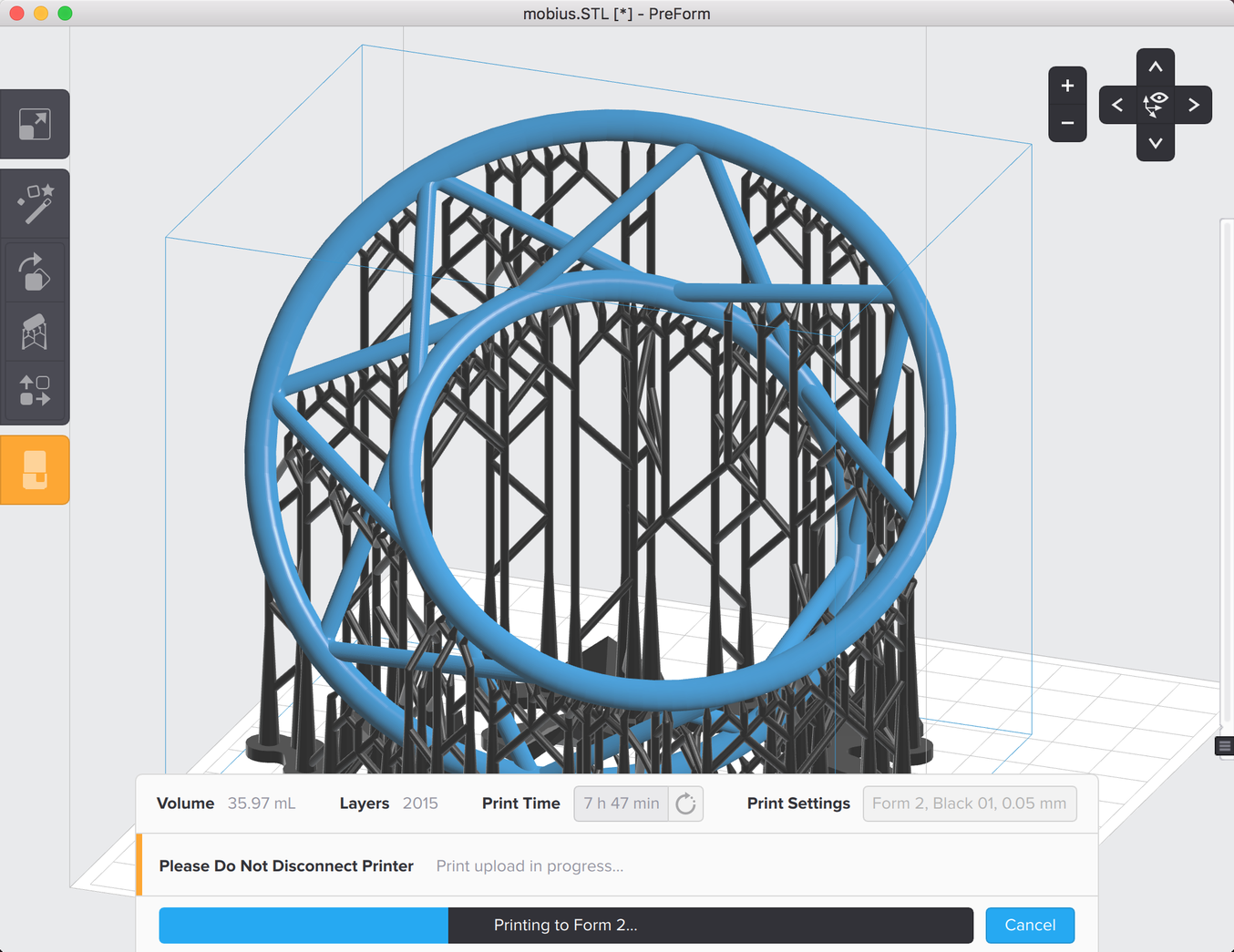
Once you click “Upload Job”, PreForm displays a progress bar as each layer of your model uploads to the printer. The Form 2 screen also displays the progress of the file transfer.
NOTICE
Do not disconnect your printer from your computer or network connection until this process is complete. The file transfer can take several minutes. It is safe to disconnect the computer once PreForm confirms the upload of your print.
Confirm the Print
Confirm the print from the Form 2 touchscreen. Make sure that your printer is ready to print and then press the button on your printer to begin the print.
TIP
For the fastest upload time, wait until PreForm completely uploads the file before confirming the print and pressing the button.