 |
VectorNav LabVIEW Library
|
|
VectorNav LabVIEW Library
|
This example walks through the entire process of recreating the Getting Started example VI within the National Instruments LabVIEW environment. During the tutorial, you will see how to connect to a VectorNav sensor, read/write registers on the sensor, perform basic configuration of the sensor, and received asynchronous ASCII and binary data from the sensor and display the data real-time in LabVIEW.
The completed VI from this example may be found at <root>/labview/examples/getting_started/getting_started.vi.
File -> New VI to create a new VI. The image below shows the new VI window.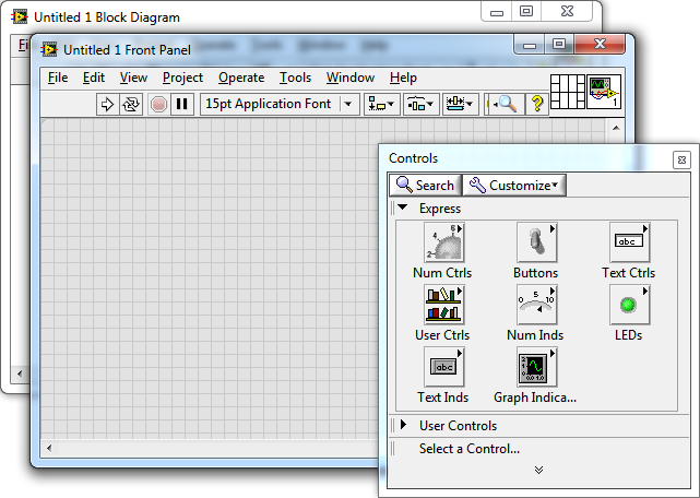
Controls palette, select Modern -> String & Path -> String Control and place two of these on the Front Panel. Retitle them to COM Port and Baudrate. Now place six number displays from Modern -> Numeric -> Numeric Indicator and title these Yaw, Pitch, Roll, Accel.X, Accel.Y and Accel.Z. Organize them so they look pretty like shown in the image below. Now also select a button from Modern -> Boolean -> Stop Button and place on the Front Panel.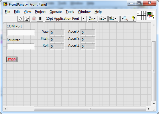
Window -> Show Block Diagram. Our collection of control backends should already be visible here. Now what we want to do is access functions from the VectorNav .NET Library so that we can connect and receive data from the VectorNav sensor. To do this, we will first call a static method of the EzAsyncData class to create our access object for sensor data. From the Controls palette, select the control Connectivity -> .NET -> Invoke Node (.NET) and place on the Block Diagram. Right-click the new node and select Select Class -> .NET -> Browse.... Here we can now browse to the compiled DLL of the VectorNav .NET Library. Click the Browse... button and select the DLL located in the library at <root>/net/bin/win32/VectorNav.dll (you may also prefer moving the file to the folder where you will be saving your VI before selecting the DLL). Now we have access to many classes and methods which are fully documented in the VectorNav .NET Library documentation but for now, we will explain the specific classes and methods used in this example. We now need to select the object we wish to use so expand the listed objects to select VectorNav.Sensor -> EzAsyncData and click OK. The class/object EzAsyncData allows simple connection to a VectorNav sensor over a serial port, and will automatically process and make available all asynchronous data it receives from the sensor. We should now be back to the Block Diagram but we still need to select the method we wish to call. Click the block's field titled Method and select the method [S]Connect(String portName, UInt32 baudrate). The [S] means the method is static and that we do not need to create an object first before calling the method. This method call now requires two parameters which are now added to the block. The first is portName and we can simply pass the output of the COM Port String Control into this parameter. The second parameter is baudrate and requires a number, so we must convert the string of the Baudrate control to a number first. Connect the output of the Baudrate control with a block from Programming -> String -> Number/String Conversion -> Decimal String To Number, then connect the output of this block with a block from Programming -> Numeric -> Conversion -> To Unsigned Long Integer. Finally connect this block's output to the baudrate parameter. Your block diagram should look like the image below now.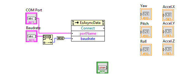
Connect method will automatically connect to a VectorNav sensor and will return a new EzAsyncData object. Our plan is to continually call the property CurrentData on this object and then display the data we get. Go ahead and place a while loop from Programming -> Structures -> While Loop. Inside the while loop, place new block from Connectivity -> .NET -> Property Node (.NET). Connect the output from the Connect method call to the input of the new block. This will allow LabVIEW to determine what type of object we are accessing enabling us to select the specific property we want on the object. Now click the Property field and select the property CurrentData from the available options. Now each time the while loop is executed, we will have access to the current data received from the VectorNav sensor. Go ahead and place the STOP button control inside the while loop and connect to the stopping condition. Also place all of the indicators inside since we will eventually be updating them inside the loop. Your Block Diagram should look similar to the image below.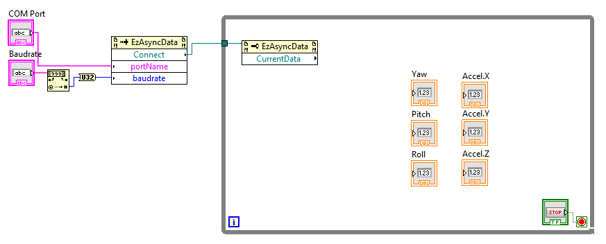
Connect method, we were given a new EzAsyncData object that needs to be closed once we are finished. Since we will be using this object for every iteration of the while loop, we just need to make sure we close it once the while loop ends. Place a block from Connectivity -> .NET -> Close Reference to the right-side of the while loop and connect the reference output from the CurrentData access to the Close Reference block. See the image below for an example setup.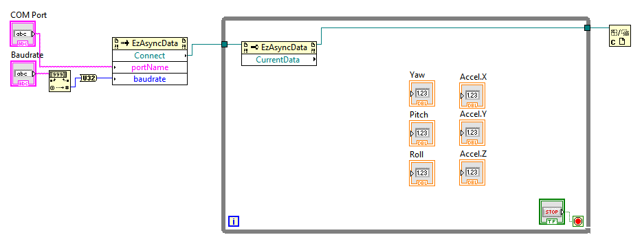
CurrentData, we must first make sure that there is valid data for us to access. For example, we will first be accessing the attitude data and quite often for the first few iterations of the while loop, the EzAsyncData will not as yet have received any asynchronous data from the sensor. This is due to the program running very fast compared to the relatively slowness of the serial communication port. Another scenario is when the sensor is not configured to output any attitude data and thus it would be invalid of us to try to access any attitude data from the CurrentData. So first we will check if there is any valid data first. Place another Property Node (.NET) block and connect the output of the CurrentData to it. Now for the Property, select the property HasAnyAttitude, which will return true or false indicating if any attitude data is present. It is possible to access the YawPitchRoll property instead but the AnyAttitude property provides a convenience method for accessing any type of attitude data received (i.e. YawPitchRoll, Quaternion or DirectionCosineMatrix data). Now place a Programming -> Structures -> Case Structure to the right and connect the HasAnyAttitude data into the Case Selector. Place the Yaw, Pitch and Roll indicators to the right-side of the case structure since depending on the current case, we will update these indicators appropriately. Your Block Diagram should look similar to the one below.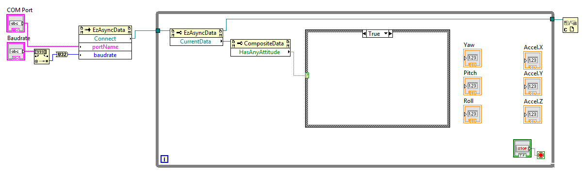
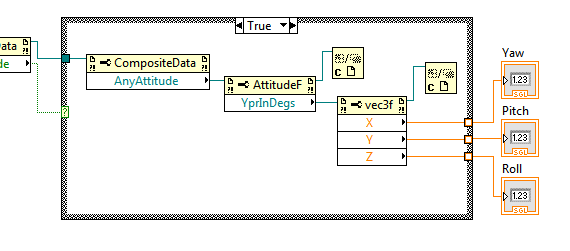
For the True case, we know we will have valid attitude data so this can be appropriately requested from the CurrentData object. Place a new Property Node (.NET) inside the case statement and connect the reference output of the HasAnyAttitude access to this block. Select the AnyAttitude property for this block. Now the object returned from this block is a generic attitude representation from which we can get attitude information in a variety of formats. We are interested in displaying yaw, pitch, roll in degrees for now, so place another Property Node (.NET) connected to the AnyAttitude output and select the property YprInDegs. This property will return a 3-component vector from which we can access XYZ components and finally display these values. Place once more another Property Node (.NET) connected with the YprInDegs output. However, now we want to access 3 properties from this object so add more property accessors to the new block by right-clicking on it and selecting Add Element twice. Now for the three available property accessors, select the properties X, Y, Z properties. Now wire up the outputs of the X, Y, Z properties to the Yaw, Pitch, Roll indicators appropriately. Finally, add Close Reference blocks for the YprInDegs and XYZ property accessors since we have retrieved the information we need and can close the references. See the image below for the resulting True block layout.
Note, if you are concerned about the red dots that appear on the Yaw, Pitch, Roll indicators, you can get rid of these by right-clicking each indicator and selecting Representation -> SGL. These red dots are merely warnings since the indicators default to displaying a double-precision data type while the sensor is only reporting attitude data in single precision.
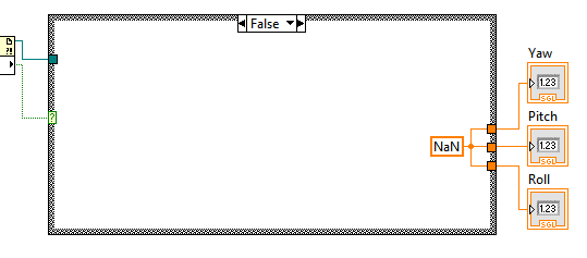
We have now handled the case when there is actually attitude data available, however, we need to handle the case when there is no attitude data available. Switch to the False case of the case structure. Place a constant from Programming -> Numeric -> DBL Numeric Constant inside the case structure and type "NaN" inside to indicate not-a-number. Connect the output of this constant to the three data outputs of the case structure. Refer to the image below for the current layout.
Note, you may receive the red dots on the numeric indicators again. This can be fixed by right-clicking the constant block and selecting Representation -> SGL.
CompositeData reference. This will need to be done for both the True and False cases. Place another Property Node (.NET) with these feed through reference connected and select the property HasAnyAcceleration. Place another case structure to the right of this node and connect the boolean output to the case selector.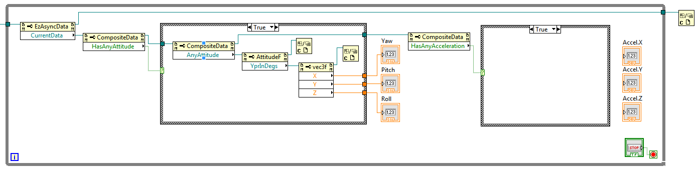
True case, place a Property Node (.NET) to access the AnyAcceleration property. This property is a little bit different than the AnyAttitude property since it just immediately returns a 3-component vector. Add another Property Node (.NET) to access the XYZ components and connect these with the Accel.X, Accel.Y and Accel.Z indicators. Add a Close Reference block to the end of the vec3f access block. Now switch to the False case and add another "NaN" constant block connected to the data outputs for the indicators. Finally, feed forward though the case structure the CompositeData reference and finish off with a Close Reference block. The image below shows the completed right-side of the VI for accessing acceleration data.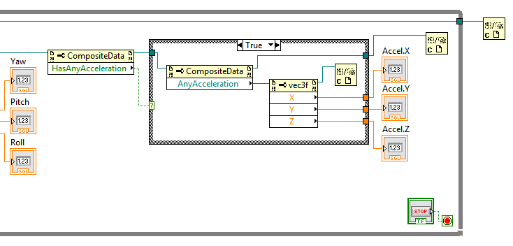
COM Port and Baudrate and press Run. The VI should immediately connect and start displaying yaw, pitch, roll and acceleration data. If data is not displayed, use the Sensor Explorer software to double-check that the sensor is configured to output these data types. This example will work with data types from either ASCII or binary asynchronous outputs. See the VI located in Getting Started for what the completed VI should look like. 1.8.10

