Planes Manager
Use the Planes Manager to select, create, edit, and manage planes. The list in the Planes Manager shows all of the planes defined in the current file. With the Planes Manager's controls and menus, you can manipulate these planes as required by your part. You can also modify the Planes Manager itself. Some of the ways you can use the Planes Manager are listed here:
- Float, dock, collapse, or move the Planes Manager to another monitor.
- Reorder the planes (except system planes) by clicking and dragging to a new location.
- Sort the planes on various criteria.
- Use [Shift+click] or [Ctrl+click] to select multiple planes at a time.
- Use each plane's properties panel to edit the plane's attributes.
The following section explains how to use Planes Manager, as well as describes its many parameters.
 Toolbar
| Icon | Name and Description |
|---|---|

|
Create a new plane Choose one of the following options to create a new plane using the New Plane function panel. You can name and define the plane and its origin, set a work offset, create a viewsheet, create a section view, and set other options.
|

|
Add group Creates a new group folder in the planes list. Use groups to organize your planes. |

|
Find a plane Identify a plane in the list based on the selected option.
|

|
Set your current WCS, construction plane, and tool plane with their origins to the selected plane Sets your current WCS, construction plane, and tool plane with their origins to the plane you have selected in the Planes Manager. |

|
Reset your current WCS, construction plane, and tool plane to their original state Resets the planes to the state that existed when the file was opened. |

|
Display options Select one or more of the following display options:
|

|
Follow rules Select one or more rules. The state of follow rules are preserved between sessions.
|

|
Section view Toggles the display of the Section View, which allows you to see a section of the part by cutting a plane. This toggle is the same as the Section View toggle on the View tab of Mastercam's ribbon. Use the drop-down menu to set which entities will be affected by the section view. You can also choose Show Caps, which fills in the section of the part with a solid cap. |

|
Show gnomons Select to toggle the display of plane gnomons. This toggle is the same as the Show Gnomons toggle on the View tab. To display a plane gnomon for a plane that is not the current WCS, Cplane, or Tplane, the Display column must be selected. Select one or more of the following options:
|
|
Search Search for planes by name. |
|

|
Sort Toggles plane sorting. Use the drop-down menu to choose the search parameters. |

|
Filter Filters the planes shown in the list based on the parameters you select. |
Plane list indicators
Plane icon
Indicates the type of machine using the plane or the type of link specified for the plane. A check mark indicates the plane is used somewhere in the file such as in an operation, a viewsheet, or your current construction plane (Cplane). To determine how the plane is used, right-click the plane, and select Report to view a plane-usage summary. The table following shows the icons used in the plane list.

|
Mill |

|
Parent Link |

|
Lathe X |

|
Child Link |

|
Lathe D |

|
Parent/Child Link |
Name
Shows the name of the plane. Lathe users see a pre-defined plane, Lathe Z = World Z. Use it when your lathe part is drawn vertically, and its axis of rotation is the world Z-axis. Setting this plane as the WCS maps the axes to a standard lathe coordinate system.
Work offset
Displays the work offset number that is associated with the plane or displays an icon that indicates that an automatic offset will be assigned.
G
Indicates that the plane is used as the current Gview. To change the Gview, click G on the plane you want to select.
WCS
Indicates the plane is used as the current working coordinate system (WCS) plane. To change the WCS, click WCS on the plane you want to select.
C
Indicates the plane is the current construction plane (Cplane). To change the Cplane, click C on the plane you want to select.
T
Indicates the plane is the current tool plane (Tplane). To change the Tplane, click T on the plane you want to select.
Lock/Unlock
Indicates that the respective plane is locked from being edited or deleted. System planes cannot be locked. To show this setting, choose Lock/Unlock from the plane's More actions menu.
Display gnomon
Click a plane's Display gnomon button to show or hide its gnomon in the graphics window.
Section view
Indicates that a section view is created from the respective plane when Section View is on.
More actions (...)
Displays the plane's More actions menu. For more information, see the section "More actions menu" later in this topic.
Properties
Name
Specifies the plane's name.
Work offset
Assigns a work offset value to the plane. When you use the plane for a Tplane and create a toolpath, Mastercam outputs the work offset when you post the operation.
-
Manual: Enables the value field so you can enter a work offset number.
-
Automatic: Automatically assigns a matching work offset number during post processing (if one exists), or the next available number if no matching work offset number is found. Work offsets can exist assigned to planes, in a toolpath operation's Tplane, and in a transform operation's NCI. Mastercam searches for existing work offset numbers in that order. The value for Automatic is -1 and Automatic is the default setting.
You can specify the default setting for Work offset in the Planes page of the System Configuration dialog box.
Work offset (entry field): Specifies the work offset for the plane.
Get unique: Generates a unique work offset value. Click Get unique again to assign the next unused work offset value. Subsequent clicking of Get unique toggles between the first unique work offset value and the second available value. This option is available only when Work offset is set to Manual.
If you duplicate a plane and only change the plane's name (keeping all other attributes the same), the work offset value will be the same as the original plane.
X origin/Y origin/Z origin
Displays the origin of the plane from the main system origin in view coordinates. The coordinates along each axis are relative to the plane axes. Type new coordinates in the fields, or use the clipboard functions in the right-click menu to update origin values. Alternately, right-click in an Origin field and select X, Y, or Z coordinate of a point. Select a new origin in the graphics window.
To display world coordinates, choose Display origin values in world coordinates in the Display options drop-down menu.
Select origin
Returns you to the graphics window to select a new origin for the currently selected plane.
Reset origin
Resets the selected plane’s origin coordinates to X0,Y0,Z0 and removes any existing associations with geometry.
Associative origin
Indicates whether the plane's origin is associated to geometry and if the origin will update when that geometry is moved. This checkbox is enabled upon plane creation if the plane can be associated to the geometry used to create the plane.
If the Cplane, Tplane, Gview, or WCS is assigned to that plane they will be updated as well. Planes cannot be set to Associative origin after they are created. If you edit a plane and deselect Associative origin, you will not be able to associate the plane and its geometry again.
Associative orientation
Indicates whether the plane's orientation is associated to geometry and if the orientation will update when that geometry is moved. This checkbox is enabled upon plane creation if the plane can be associated to the geometry used to create the plane.
If the Cplane, Tplane, Gview, or WCS is assigned to that plane they will be updated as well.
Planes cannot be set to Associative orientation after they are created. If you edit a plane and deselect Associative orientation, you will not be able to associate the plane and its geometry again.
Color
Sets the selected plane's color. This is the color Mastercam uses to show the plane in the graphics window.
Comment
Type a comment in this field, which will appear in the post processed NC code to communicate plane information to other users.
More actions menu
Edit
Opens the Edit Plane function panel so that you can modify the selected plane. You can only edit user-defined (named) planes. Main system planes (Top, Front, Back, Bottom, Right, Left, Isometric, Reverse Isometric, and Trimetric) cannot be edited.
Rename
Changes the name of a plane. You can only rename user-defined planes. You cannot name a plane Gview, Cplane, Tplane, or WCS; or rename the main system planes (Top, Front, etc.).
Delete
Select one of the following options:
- All unused: Removes all planes that are not being used from the planes grid and part file. You cannot delete any of the main system planes.
- Selected: Removes the selected plane from the planes grid and part file. You cannot delete any of the main system planes or any planes that are in use.
Group
Places the selected planes into a group.
Ungroup
Removes the selected planes from a group.
Move
Moves the selected planes to a group.
Lock/unlock
Locks or unlocks a user-defined plane. System planes cannot be locked/unlocked. Select one of the following options:
- Selected: Locks any selected planes from being edited or deleted, and displays the lock icon in the Name column. If a plane is locked, certain dialog box parameters and right-click menu options are also disabled. Choose this option to unlock a previously locked plane.
- Lock all: Locks all user-defined planes and displays the lock icon in the Name column.
- Unlock all: Unlocks all previously locked planes.
Link/unlink
Links or unlinks a user-defined plane. System planes cannot be linked/unlinked. Select one of the following options:
- Link selected: Opens the Plane Selection dialog box, where you can select a parent plane to link to the selected plane. Linked planes maintain a parent-child relationship. When the parent plane changes, the child planes linked to it will also change. If you change the orientation of the parent plane, the child planes move with it.
- Unlink selected: Unlinks the selected child plane from the parent plane.
- Unlink all: Unlinks all planes in the part file.
Rotate incremental
Opens the Rotate plane dialog box, where you change the orientation of the selected plane by rotating it by set values around each axis.
Select origin
Returns you to the graphics window to select an origin for the plane.
Set as
Sets the plane as the Gview, WCS, Cplane, or Tplane.
Set color
Sets the plane color shown in the gnomon.
Display plane gnomons
Toggles Show Gnomon on and displays the plane based on the selected option:
- All: Toggles the Display column on for all planes and displays the plane gnomons in the graphics window.
- Selected: Toggles the Display column on for planes selected in the Planes Manager and displays the plane gnomons in the graphics window.
- None: Toggles the Display column off and Show Gnomons off (if on) for all planes.
Coordinate display
Changes the coordinate display of created planes to Mill, Lathe X, or Lathe D.
The View Axes Gnomon (in the lower left corner of the graphics window) will display with the selected coordinate system. When Show Gnomons is toggled on and Display Cplane and Tplane in corner is selected, the Cplane coordinates will also display with the selected coordinate system.
Fit origin
Changes the view in the graphics window to include both the part and the origin.
Select related link planes
In the plane list, selects all planes that are linked to the selected plane.
Create relative
Opens the Create Relative Planes dialog box, where you can create named planes that are defined relative to the selected plane.
Duplicate
Creates a duplicate of the selected plane. The duplicated plane uses the same name as the selected plane with a -1 suffix (Plane-1). A duplicate plane made from a locked plane is unlocked when duplicated.
Report
Opens your default editor, which displays a report with detailed information about Selected, Used, or All planes.
Import
Imports planes from another part. Mastercam prompts you to select a file, and then displays all of its planes. Select the planes to be imported.
How do I...
How do I understand the difference between relative planes, linked planes, and associative planes?
Relative planes, linked planes, and associative planes rely on a connection with other planes or geometry within the part file.
- Relative planes are planes created in predefined spatial relationships relative to the selected plane.
- For example, create Plane-2 in the Planes Manager and right-click it to select Create relative. In the Create Relative Planes dialog box, select only Right side. Mastercam creates a plane that is a right-sided view of Plane-2.
- Relative planes are linked by default. To unlink them, you can deselect Link in the Create Relative Planes dialog box.
- Linked planes have a parent-child relationship; the selected plane is dependent on the plane to which you link it.
- For example, create Plane-3 and link it to Plane-2. When you move Plane-2, Plane-3 will also move the amount necessary to retain its spatial relationship (the amount of transformation to get from Plane-3 to Plane-2) to Plane-2.
Linked planes use icons to display their relationship in the Planes Manager, as shown in the following image.

- Associative planes maintain a relationship with the geometry used to create them. When you create a new plane from geometry, entity normal, a solid face, or from the Dynamic Gnomon, Associative origin and Associative orientation are selected by default to maintain the predefined spatial relationship of the plane's view and origin relative to the geometry used to create the plane.
- For example, create Plane-4 from geometry, entity normal, a solid face, or from the Dynamic Gnomon. In the Advanced tab of the New Plane/Edit Plane function panel, Associative origin and Associative orientation are selected by default. If you transform the geometry you used to create the plane, the plane origin and orientation will transform to maintain their spatial relationship to the geometry.
If you break a plane origin's associativity, you can still reestablish it when selecting a new origin for the selected plane.

- Broken orientation associativity cannot be reestablished.
- Deselect Associative origin and Associative orientation when you are creating a plane from temporary guides or construction lines that you plan to delete.
How do I use
work offsets?
In the parameters section of the Planes Manager, you can assign a work offset number to the currently selected plane.
-
Select Manual and type a 0 (zero) in the value field to assign the base offset in your control's numbering system (for example, G54 for Fanuc-style offsets), or higher integers to increment from the base, (for example, enter 2 for G56).
NOTEThese values are determined by your post processor.
- Select Automatic to automatically assign a matching work offset number (if one exists), or the next available number if no matching work offset number is found.
- When editing a plane, choose Get unique to have Mastercam review your model and assign an unused or new offset number.
How do I enable a translucent plane display?
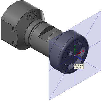
If you want to enable a translucent plane display for your planes, select Display options, Plane gnomon settings from the Planes Manager.
Then, use the settings in the dialog box to show the plane, show the grid, change the axes size, and change the plane size. You can also set the opacity of the axes and the plane display.


