Toolpaths Manager
The Toolpaths Manager is a central location where you can manage all the elements of the current job. Use the Toolpaths Manager to generate, sort, edit, regenerate, verify, backplot, and post any operation.

 How does the Toolpaths Manager affect my part file?
The Toolpaths Manager organizes toolpath information in machine and toolpath groups. Once you have generated toolpaths for the part, most activity in Mastercam takes place in the Toolpaths Manager. A toolpath operation is created in the Toolpaths Manager automatically every time you create a toolpath.
Mastercam machines operations in the order in which they display in the Toolpaths Manager. Dependent operations, such as a stock model operation, must come after the operation to which they reference. To learn how to reorganize operations in the Toolpaths Manager, see How do I use the Toolpaths Manager?.
Toolpaths cannot be created until you identify the machine properties by either selecting or creating a machine group. For more information on setting up the machine properties, please see About the Control Definition and About the Machine Definition.
What are machine groups and how are they organized?
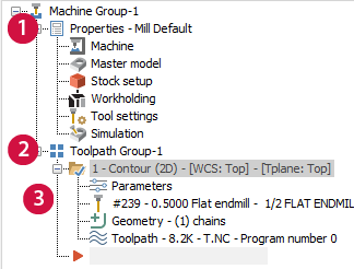
When you choose or create a machine definition in Mastercam, that information is housed in a Machine Group folder in Toolpaths Manager. When that folder is created, it is automatically populated with a machining properties folder and a toolpath group. You manually add operations to the toolpath groups.
-
Machining properties folder: A single part can have multiple machine groups, each containing machining properties folders that identify properties (i.e., support files, tooling, stock, etc.). These details are set in the Machine Group Properties dialog box or Machine Group Setup function panel, depending on the machine type. Each toolpath group listing begins with this information.
Mastercam splits these machining properties details into six categories:
-
Machine
-
Master Model
-
Stock/Job Setup
-
Workholding
-
Tool Settings
-
Simulation
-
-
Toolpath groups: Toolpath groups are subgroups of operations inside a machine group. They contain details of the operations, such as parameters, tools, and embedded operations.
These subgroups provide not only a way to logically organize your operations, but also allow quick selection of toolpaths: selecting a toolpath group automatically selects all operations within the group.
You can have an unlimited number of subgroups embedded into other subgroups.
-
Operation folders: Each operation has a name that describes the kind of machining action it includes, such as 2D Contour. A single part can have many operations that are housed in toolpath groups. Each operation has at least four parts:
-
Parameters
-
Tool definition
-
Part geometry
-
Toolpath data
-
For more information about icons and functions within the Toolpaths Manager list, refer to the Toolpaths Manager Icons help topic.
How do I use the Toolpaths Manager?
The Toolpaths Manager allows you to interact with your machine and toolpath groups in the following ways:
- Use toolbar buttons to control the machine and toolpath groups within the manager. See Toolbar buttons to learn about the toolbar functions.

-
Create new operations and groups, edit existing operations, view part details, and control operations in your file using the right-click menu. For information on all right-click options available to you, refer to the Toolpaths Manager Right-click Menu help topic. To learn about creating multiple machine groups, see Working with Machine Groups.
-
Organize new and existing operations and groups.
Once a group has been set up in the Toolpaths Manager, an operation insert arrow (shown below) appears, indicating the point where new operations will be inserted into the parent group.

The default position of this insert arrow is at the bottom of the list of current operations. To create an operation somewhere in the list other than at the default position, drag the arrow and drop it after the operation you want the new operation to be created. You can also use the Insert Arrow navigating buttons (shown below) located at the top of the Toolpaths Manager.


You can also organize operations and groups by using the Toolbar buttons, the Toolpaths Manager Right-click Menu, and standard Windows commands for functions such as copy, paste, select multiple, and delete.
To learn more, see Moving and Copying Items in the Toolpaths Manager and Working with Machine Groups.
-
Quickly access toolpath functions by clicking on an operation icon. See Toolpaths Manager Icons to learn more about machine group and toolpath group icons.
-
As with all Mastercam managers, you can also dock, resize, and personalize the Toolpaths Manager to suit your work style. See Docking/Undocking, Re-Sizing, and Closing Toolpaths/Solids Manager for more information.
Toolbar buttons
| Icon | Name | Description |
|---|---|---|

|
Select all operations |
Selects all operations listed in Toolpaths Manager. Use to post, verify, regenerate, or perform other functions on all operations within a job. |

|
Select all dirty operations | Selects all dirty (invalid) operations in the Toolpaths Manager. Use to post, verify, regenerate, or perform other functions on selected operations within a job. |

|
Regenerate all selected operations | Recalculates selected operations. |

|
Regenerate all dirty operations | Recalculates all dirty (invalid) operations. |

|
Dependencies |
Toggle on to automatically select or regenerate dependent operations.
|

|
Backplot selected operations | Simulates tool movement for selected operations using Classic Backplot. |

|
Verify selected operations |
Simulates machining and material removal for selected operations using Mastercam Simulator.
|

|
Simulator options | Opens the Simulator Options dialog box. |

|
Post selected operations | For a non-Mill-Turn part, runs the post processor for selected operations and creates the NC program. If you are in a Mill-Turn machine group, this button runs Sync Manager. For more information, please see About Post Processing. |

|
High feed | Optimizes feed rates for selected operations. For more information, please see Highfeed Machining. |

|
Delete all operations, groups and tools |
Deletes all machine groups in Toolpaths Manager except the last one in the list. This deletion includes operations, tools, and machine definitions. CAUTION
You will not be able to undo this deletion. |

|
Help | Displays Mastercam's Help. |

|
Toggle locking on selected operations |
Locks and unlocks selected operations. Locking the operation prevents you from regenerating the toolpath. NOTE
If you regenerate the toolpath after unlocking it, you will lose any changes you have made. |

|
Toggle display on selected operations | Displays and hides selected operations in the graphics window. When a part contains a mixture of operations that are displayed or hidden, clicking Select all operations and then Toggle display on selected operations hides all toolpaths in the graphics window. Clicking Toggle display on selected operations again shows all toolpaths. |

|
Toggle posting on selected operations |
Enables and disables posting on selected operations. Note that the symbol indicates that posting is off for the operation.
|
|
|
Move insert arrow down one item | Moves the insert arrow down past the next operation. The insert arrow controls where new operations will be inserted. Its default position is at the bottom of the list of operations. |
|
|
Move insert arrow up one item | Moves the insert arrow up past the previous operation. Its default position is at the bottom of the list of operations. The insert arrow controls where new operations will be inserted. |

|
Position insert arrow after selected operation or after selected group | Moves the insert arrow down past the selected operation or group. Its default position is at the bottom of the list of operations. The insert arrow controls where new operations will be inserted. |

|
Scroll window so insert arrow is visible | Scrolls the viewing area to display the point at which you can view the insert arrow. |

|
Only display selected toolpaths | When enabled, displays toolpaths in the graphics window only for the operations you select in Toolpaths Manager list. This state will persist across Mastercam sessions. |

|
Only display associative geometry | When enabled, displays all geometry associated with the selected operations, provided that the geometry is not hidden or blanked and is on levels that are visible. This state will persist across Mastercam sessions. |

|
Advanced display |
Toggles the toolpath display, allowing you to see the differences between individual toolpath entities such as entry motion and endpoints by modifying their color and display state. Use the drop-down to hide or show different sections of the toolpath. For more information, see Using Advanced Display. |

|
Tool setup | Opens the Tool Setup Manager dialog box. Use the dialog box to establish the physical orientation and positioning of tools used in the active machine group. |

|
Edit reference positions |
Opens the Machine Reference Position Manager dialog box. Use to edit the location of the reference positions. |


