Edit Spline panel
Use the Edit Spline function to refine and prepare splines for any application. Edit Spline works on all NURBS splines and converts any selected lines, arcs, or Parametric splines to a NURBS spline. Modify the tangencies and magnitudes of the curve at the spline’s node points, or edit tangencies at the vectors of control points. You can move a node point, rotate the tangent vector, or change the length of the tangent vector to edit the curve at the node. You can also move control points lying off the spline to obtain similar results.
For more control and finer adjustments, add or remove node points, or increase the number of control points.
When you select a control point, Mastercam may auto-select additional control points to preserve tangent continuity.
 How do I repair a non-tangent spline?
The Edit Spline function displays a "broken" vector set to graphically indicate when the selected spline has a sharp corner and is not tangent at the node point.
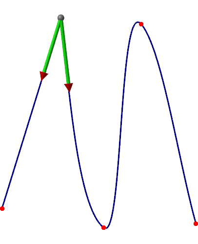
When you see this condition, simply click the shaft of either vector arrow to force a tangency with the opposite vector.
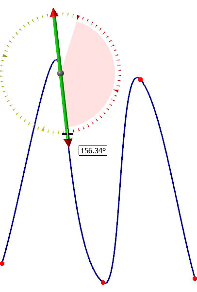
How do I use the curvature comb?
The curvature comb represents the curvature of the spline and can show if the curvature is continuous. Although curvature continuity is not mandatory for good spline data, some applications require curvature continuity at node points.
Use the options on the Advanced tab to enable and adjust the display of the curvature comb. Control the display of the curvature vectors by adjusting the value in the Scale field. Control comb spacing with the Chord height and Number options.
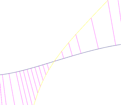
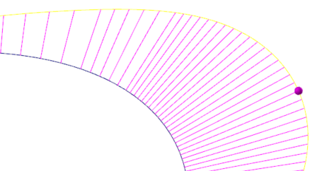
The yellow curve that displays when you enable the curvature comb is the curvature offset curve. A physical break in this yellow curve indicates that curvature continuity is lost.
The purple lines represent the curvature vectors and point away from the center of curvature.
Use the purple grab handle that displays on the yellow curve to adjust the size of the purple curvature vectors. This allows for improved visibility and magnifies smaller gaps in continuity. The purple grab handle is an alternative to entering a value in the Scale field.
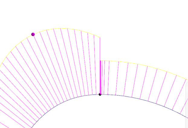
Use the Edit Spline function to manipulate the spline so that its curvature is continuous. When the yellow curve is connected at the nodes, the spline has curvature (G2) continuity; and when the yellow curve is tangentially continuous (smooth) at the nodes, the spline has flow (G3) continuity which is required for class A spline curves.
The curvature comb can also show inflection points on the curve. These are points where the curvature changes its sign and points in the opposite side of the curve. Inflection points exist wherever the curvature offset curve (yellow curve) crosses the spline.