Disassemble panel
Use the Disassemble function to separate solid or mesh bodies and organize them in a specified plane. Select the bodies to disassemble, set options such as the spacing and start point, and click OK in the Disassemble function panel.
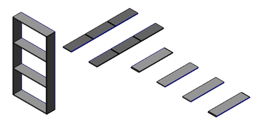
 How can I
use Solid Disassemble to nest solid and mesh bodies?
How can I
use Solid Disassemble to nest solid and mesh bodies?
From the Transform tab, choose Geometry Nesting. Then, on the Parts tab, right-click in the Part list, and choose Disassemble solid and/or mesh from the pop-up menu.
How do I control the orientation of the disassembled solids?
By default, Mastercam orients disassembled solid and mesh bodies on their largest, flat face. To control the orientation of the disassembled solids, enable Face Selection and disable Body Selection on the Selection Bar.

Mastercam will orient disassembled solid bodies on a specific face, when selected.
Also, you can use the Face Color option to orient colored faces towards the layout plane. You might use this function, for example, if you need to separate assembly parts into the same orientation.
-
Start the Model Prep, Disassemble function.
-
In the Face Color box, click the Sample color button, and, in the graphics window, select the face color to use. When you select a color, Mastercam automatically selects the Color checkbox, activating the function.
-
Select the geometry to disassemble. Mastercam orients the colored faces to the layout plane.
By default, Mastercam separates bodies in an assembly by placing the larger face towards the layout plane. This default behavior takes precedence even when orienting solid bodies using a face color. For this reason, for face color orientation to work, the colored face and its opposite face must be the same size.
How can I separate disassembled solid and mesh bodies to easily create toolpaths?
Select At origin on levels under Placement, enable Move to Levels, and Create viewsheets for each level. Mastercam will separate and move each disassembled body to the origin, on its own viewsheet and level, making it easier to select geometry and create toolpaths on individual disassembled bodies.


