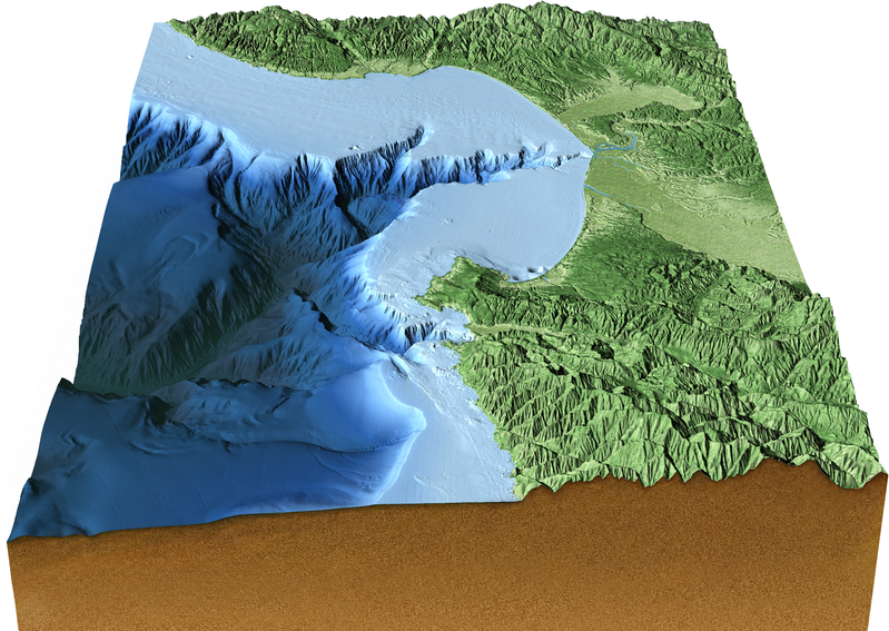
© MBARI 2000 (image: Fierstein)
Terrain Relative Navigation (TRN) Documentation
About TRN
- What is TRN?
- TRN (Terrain Relative Navigation) is comprised of algorithms that enable autonomous platforms such as AUVs to use real-time bathymetry data to locate and navigate relative to a map. In this context, TRN is implemented as a software library (libtrnav), which may be used to develop TRN applications for different vehicles (platforms).
- How is TRN used?
- Observing change is fundamental to understanding processes that affect the ocean. Being able to return to a specific place on the seafloor with high precision is not trivial. Even an inertial navigation system (INS) is subject to drift over the time scales used for mapping, for example, and typically requires acoustic updates from a ship to navigate with adequate precision.
By navigating relative to a map, autonomous vehicles can, for example, quickly and independently find and follow previous survey lines, enabling researchers to make better comparative observations, while potentially freeing valuable ship resources.
TRN has been used in MBARI's Ocean Imaging program to enable repeat mapping missions to help characterize geological processes and observe changes in areas of interest, e.g. an undersea volcano at Axial Seamount. TRN has been integrated with a variety of platforms, including MBARI's Dorado and Tethys AUVs, Woods Hole's Sentry AUV, and the MB-System open source mapping tools software.
- Observing change is fundamental to understanding processes that affect the ocean. Being able to return to a specific place on the seafloor with high precision is not trivial. Even an inertial navigation system (INS) is subject to drift over the time scales used for mapping, for example, and typically requires acoustic updates from a ship to navigate with adequate precision.
- How was MBARI TRN developed?
- TRN at MBARI was developed in a collaboration between Steve Rock's Aerospace Robotics Lab at Stanford and MBARI.
Acknowledgements


TRN Contributors
| Stanford | MBARI |
|---|---|
|
Stephen Rock Debbie Meduna Shandor Dektor Jose Padial David Stonestrom |
Dave Caress Rich Henthorn Rob McEwen Kent Headley AUV Operations Group R/V Rachel Carson Crew ROV Ventana Pilots |
About Terrain Relative Navigation
ver: local build
Repository
https://bitbucket.org/mbari/trn-doc-md/src/main
Maintainers
headley@mbari.org
henthorn@mbari.org
TRN User's Guide
Introduction
TRN is an algorithm that produces a best estimate of a vehicle’s position by combining a dead-reckoned measurement of its motion (e.g. velocities from a DVL or AHRS) with measured ranges to the seafloor (e.g. from a DVL, multibeam sonar, atlitmeter, etc). Specifically, the goal of the algorithm is to estimate at every time step the Northings, Eastings and Depth (NED) position of the vehicle with respect to a bathymetry map stored on-board. That is, the vehicle’s position is localized with respect to the terrain, not to GPS coordinates. Importantly, the goal also includes estimating the confidence in that position (covariance). This metric provides a means of determining whether the TRN position estimate should be accepted by the vehicle’s navigation and control system.
To accomplish this, the TRN algorithm employs a Particle Filter (PF) implementation of an Extended Kalman Filter (EKF). An EKF is required because the equations used to propagate the estimate are nonlinear. A PF implementation is chosen for several reasons. One is that the convergence of EKFs is known to be highly dependent on the accuracy of the initial estimate, and this is problematic for many field applications. Initial estimates can be off by hundreds of meters or more, for example due to a long descent from the surface with no bottom lock and hence poor navigation. Another is that the contours in the terrain can be similar at multiple locations, which creates multiple possible potential solutions for the algorithm to consider.
The core of the EKF and the PF is an iterative two-step process. First is a Process Update (or Position Update). Second is a Measurement Update. In the Process Update, the equations of motion for the vehicle are propagated from one time step to the next. This is typically done by integrating the measured velocity (e.g. from a DVL or IMU) or accepting a delta-position change from an INS. In the Measurement Update, range measurements from an acoustic device (e.g. DVL, altimeter, multibeam, etc.) are compared to range measurements calculated from the estimated vehicle location in the bathymetry map. The errors in these range measurements provide the innovations that are used to generate corrections to the vehicle position calculated in the Motion Update.
The difference between an EKF and a PF is that the EKF propagates these steps using known equations, and the PF uses a numerical, Monte-Carlo approach. Specifically, the PF propagates multiple (e.g. 10,000 or more) hypothesized locations of the vehicle (particles) plus weightings on each particle that quantify how well the predicted range measurements match the measured ranges. The PF implementation results will match the EKF equation results exactly when the number of particles goes to infinity.
TRN can be run real-time or as a post processing aid. When run in real time, the best estimates of the vehicle’s position provided by TRN can be used to correct the navigation data used by the control system. This eliminates drift errors typical of most onboard dead reckoning navigation algorithms (e.g. DVL based AHRS) as well as any georeferencing errors in the bathymetry. An example of a mission enabled by TRN is returning to a site of interest (indicated as a point on a map) without using any external infrastructure. Acoustic arrays, beacons or surface aiding navigation aids are not required.
The navigation accuracy provided by TRN is typically on the same order of magnitude as the resolution of the bathymetry map being used. In work using 1m maps, TRN accuracy of 2 to 3m meters is typically seen.
TRN is meant to be used to provide a correction to the navigation data in closed-loop applications. It is not intended as the sole navigation solution. The reason is that navigation loops are often closed at high sample rate (e.g. 0.4seconds) and the sample rate of TRN is typically slow (e.g. 4 seconds). One reason for this slow rate is that a PF implementation of TRN is computationally expensive. Another critical reason is that a slow rate is required to ensure that all the measurement data entering the TRN algorithm is uncorrelated.
II. Sample Mission:
Before describing how TRN operates, a description of the output produced by TRN can be demonstrated using a sample mission performed at Portuguese Ledge by an LRAUV equipped with a DVL. The map used for this mission had a resolution of 1m. The vehicle’s navigation system used the DVL, compass and attitude sensors (pitch and roll) to calculate a dead-reckoned solution. This type of system is called an AHRS (Attituded Heading Reference System). The vehicle’s control logic included an integral loop which forced the error between the AHRS solution and the commanded path to go to zero.
The goal of this mission was to fly a trajectory consisting of straight lines between four waypoints specified on a bathymetry map. This mission was flown twice. In the first run, the path was flown using the unaided, baseline navigation system on board the vehicle. In the second, the navigation solution was corrected with the TRN algorithm. In each mission, the vehicle made two passes around loop.
The resulting path for the first run is shown in Figure 1. The target waypoints are shown as red stars. The black line in the figure is the recorded AHRS path. The blue line is the best estimate of the true path provided by TRN. The path starts just above the Eastern most waypoint and ends with the AUV approaching that same waypoint from the Northeast.
As can be seen in the figure, the AHRS estimate of the path converges to a sequence of straight lines connecting the waypoints as expected. However, this path exhibits significant error as shown by the blue TRN path.
There are several reasons for this error. First is that the map used in this case is known to have georeferencing errors (approximately 20m), so an offset is expected. Second, the offset is large because a dead-reckoning error had accumulated as the vehicle approached the start of the mission. This often occurs if the vehicle has suffered poor navigational performance while the DVL was out of contact with the seafloor (e.g. during a spiral down maneuver from the surface). Finally, there is a drift in the AHRS navigation which is common for any dead-reckoned solution and can be caused by uncertainties in the measured velocities as well as slight misalignments in the compass, DVL and attitude measurements.
Figure 2 plots the second important quantity provided by TRN. This is the confidence the TRN algorithm has in its best estimate of the vehicles position. Plotted is the covariance of the estimate (square of the standard deviation) for both the Northings (blue) and Eastings (black) estimates. As shown, these covariances hover between about 1 and 4 m^2 (i.e. standard deviation of 1 to 2m) except for a section of the path near the middle of the mission where the uncertainty spikes.
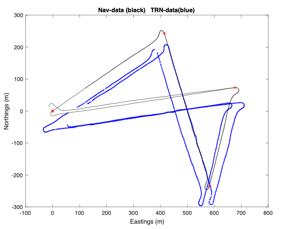
Fig 1: NED path between 4 waypoints (red *). AHRS data (black). TRN data (blue)
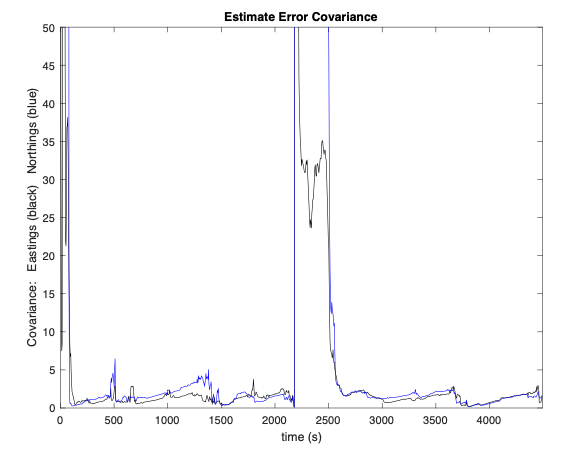
Fig 2: Covariance of the Eastings (black) and Northings (blue) TRN estimate of the TRN
The results for the second run are shown in Figure 3. In this case, the path used to control the vehicle incorporated the corrections provided by TRN. There are two curves in this figure. The blue curve is the TRN solution. The black curve is the corrected navigation data. Again, the navigation error is driven to zero by the integrator and the true path now matches the desired path. These curves overlap. (The nav data are updated every 0.4 seconds. The TRN data are updated every 4 seconds.)
The important thing to note is that the initial condition errors, the map georeferencing errors and the dead-reckoned drift have all been eliminated in the vehicle’s navigation data. The vehicle accurately follows the desired path.
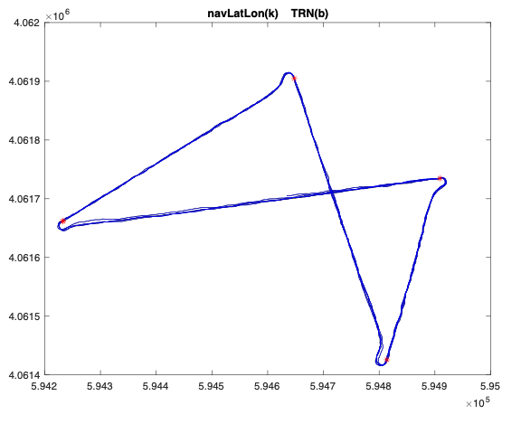
Fig 3: NED path between 4 waypoints (red *). AHRS data with TRN correction (black). TRN data (blue)
The only caveat to note is that the TRN estimate is a best estimate of the path, not necessarily the true path. This is a stochastic system, and the quality of the estimate depends on the noise and uncertainty in the data.
The parameters that describe this uncertainty and guidance on how to choose them are provided below. To begin, the basic operation of the Particle Filter used in the TRN algorithm is presented.
Summary of PF operation
As stated above, a particle filter operates by propagating a large number (e.g. 10,000 or more) hypothesized positions of the vehicle. Each particle consists of a Northings value, an Eastings value and a depth value. At every time step, beams are projected from each particle and their lengths are calculated (e.g. where the beam hits the bathymetery map).
This requires knowledge (i.e. configuration parameters) of the beam orientations with respect to the vehicle and measured values of the vehicle’s orientation (roll, pitch and yaw). How well the beam lengths match the measured beam lengths provides a metric of how likely each particle’s NED values correspond to the correct location of the vehicle.
The process (or motion) update performs the first step in this procedure. It calculates the motion of the vehicle between time steps and applies that motion to every particle. This can be done by integrating the equations of motion of the system or by measuring the change in position reported by the vehicle’s INS (the default mode in the TRN code). Random noise (a user defined input: dritRate) is then applied to each particle’s location. This sequence is depicted in Figure 4.
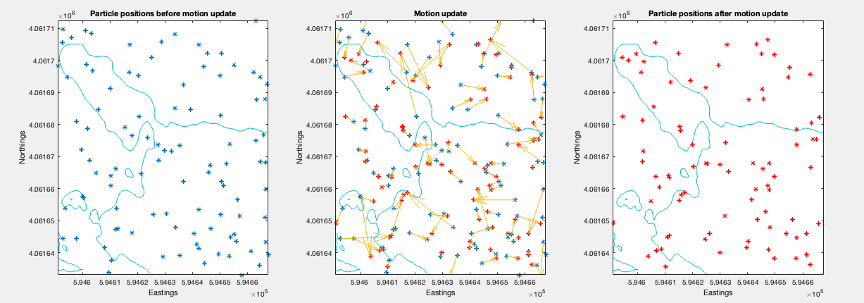
Fig 4: The Process Update: (a) particles before update, (b) delta motion and noise applied, (c) resulting particles
In the measurement update, the beam lengths associated with each particle are computed and a random noise is added (a user input: percentrangeerror). The resulting full set of particles with their associated weights defines the likelihood score for every hypothesized location.
Figure 5 depicts the data used in the measurement update to calculate the likelihood score for a particle. Shown is a sonar beam projected to a stored bathymetry map from a vehicle located at the particle’s position. The difference between the length of the measured beam and the distance to the map is the error in the measured range.
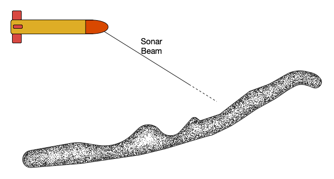
Fig 5: The Likelihood score is computed by comparing a meaured beam length to the distance to the terrain map.
If there is only one beam, the weight, \(w(i)\), assigned to each is calculated as
where the quantity \((l-l_m )\) is the error in the measured range, \(\sigma\) is the standard deviation of the measurement noise, and η is a normalizing coefficient. If there are multiple beams, the error is replaced by the sum over all the beams.
At any time step, the current best estimate of the vehicle position is the particle location where the weighted mean of the likelihood score is a maximum.
Ideally, the particles used in this iterative process would span the entire space of possible vehicle locations. Computationally this is not possible when the vehicle’s position is very uncertain, however. To overcome this, a particle filter computes a bounding box for the particles based on the current estimate of the filter’s confidence in the solution. The size of this box is adjusted dynamically to be (very roughly) 3 sigma in size using a “resampling” algorithm. This algorithm moves low-weight particles to higher weighted locations while preserving the probability distribution of the particle cloud.
An example is shown in Figure 6 for the example run provided above. The black line in the figure is the uncorrected navigation data. The bounding boxes are centered on the TRN solution (blue line).
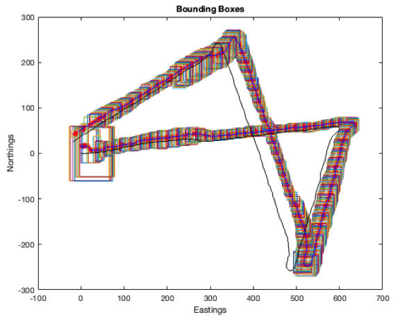
Fig 6: : Particle bounding boxes overlaid on TRN trajectory. Uncorrected AHRS data is the black line.
Figure 7 provides additional detail for the same example during a segment of the run where the PF was converging on a solution. Particle weights are plotted for five time points. The distribution of particle weights and the bounding box (red) are shown in the first column. The projections of the weights onto the Northings and Eastings directions are shown in the next two columns. The red vertical line in the location where the weighted average of the distribution is a maximum. The cyan line is the location of the peak in the distribution. As the filter converges to a solution, these two locations approach the same value.
This sequence presents one of the key advantages of using a PF implementation: a PF deals naturally with multimodal (i.e. existence of local minima) and non-Gaussian distributions. It propagates all possible solutions. The weights are reinforced or reduced as a mission continues until final convergence achieved. An EKF would likely fail to converge in this situation.
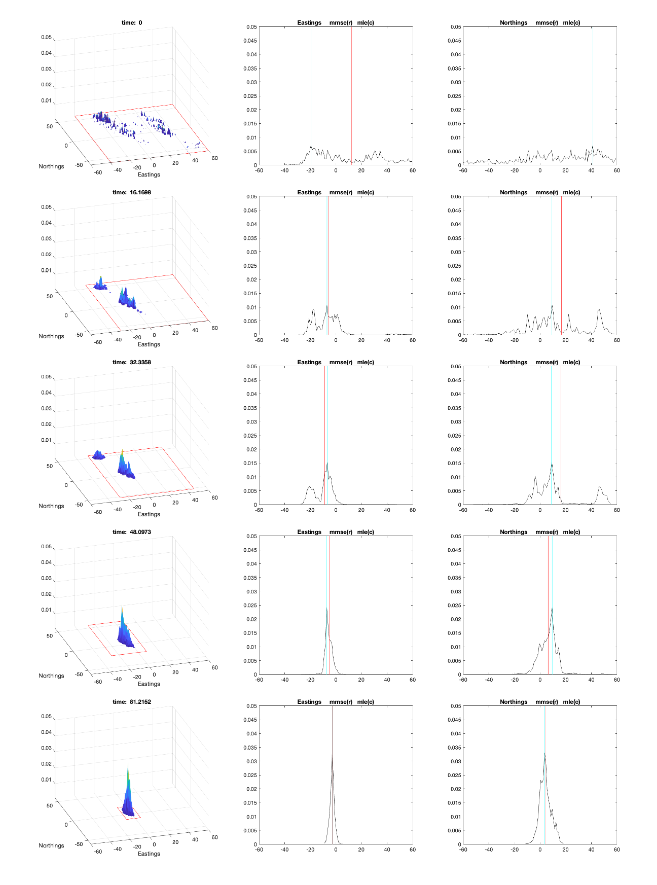
Fig 7: Sample results showing evolution of particle weights during TRN convergence. (a) partilce weights with bounding boxex, (b) weights vs.Eastings, (c) weights vs. Northings
Running TRN
Required inputs: motion data, range data and beam configuration data
The current version of TRN is configured to estimate three states: the Northings, Eastings and Depth positions of the vehicle. As described above, a measured time history of the motion inputs is required (e.g. AHRS NED values). For the measurement update, measured sonar ranges to the seafloor are required, for example DVL beam lengths, altimeter measurements or multibeam.
The motion update quantities are sampled simultaneously, and the update is typically at a constant rate, but a variable rate is acceptable.
In the measurement updates, every beam measurement is an independent input occurring at an asynchronous rate and can be treated separately. However, in practice, sonar devices often provide multiple beams simultaneously, and it is convenient to process these together using vector rather than scalar operations.
To be incorporated into the TRN solution, the configuration of every beam must be specified. This includes the location of the beam with respect to the origin of the vehicle’s reference frame (e.g. the compass) as well as its direction in the vehicle’s reference frame. Also required are measurements of the vehicle’s pitch, roll and yaw angles.
The details of how the beam data are specified and incorporated into the code are presented in SECTION: CODE DETAILS.
Required inputs: driftRate and \(percentagerangeerror\)
The PF used in the TRN algorithm, like all Kalman Filter type of estimators, is a stochastic system. It calculates a “best estimate” of the state (NED) given the inputs described above and estimates of the uncertainty in those measurements. The accuracy of these estimates depends on user defined values of the noise associated with the measurements that are used by TRN. TRN uses two variables for this purpose. The first, driftRate, describes the process (i.e. motion) noise. The second percentrangeerror defines the measurement noise.
Figure 8 demonstrates the stochastic nature of the TRN solution. Shown in the figure are 100 runs using the same input with a driftRate = 2% and \(percentagerangeerror\) = 2%. As can be seen, the TRN solution for each run is different (an expanded view of the spread is shown in Figure 9. In ideal cases, this spread is zero mean Gaussian centered about the true path.
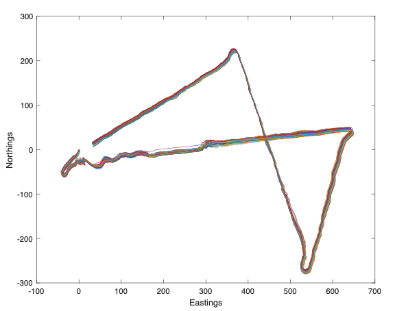
Fig 8: 100 runs for TRN for different noise values.
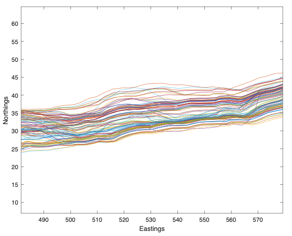
Fig 9: Expanded view of the 100 runs
The covariance (square of the standard deviation) of the state estimates (NED) produced by the TRN algorithm predicts the width of this spread. If the correct values of drfitRate and percentrangerror are chosen correctly (and all the zero-mean Gaussian noise assumptions are met), then, the width of the actual spread will match the covariance produced by the TRN, and the filter will be “consistent”.
Figure 10 and Figure 11 plot the time histories of all 100 runs of the Northings and Eastings estimates centered about the mean value at each time step. Also shown in the figure is the one sigma uncertainty bound produced by TRN (red). For a perfect choice of driftRate and percentrangeerror, roughly 63% of the curves will be inside this one sigma boundary.
NOTE: More properly, these curves would be plotted with one sigma bands on either side of the true values and not the mean values of the path. In practice however, the true path is often not known, and plots about the mean can be used. While this does provide a measure of validity of the noise parameters chosen, care must be taken when interpreting the reasonableness of the results. Looking at the smoothness of the mean is also necessary to determine the reasonableness of the result.
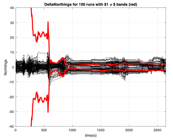
Fig 10: Northings values minus the mean for 100 runs (black). Mean standard deviation bound (red)
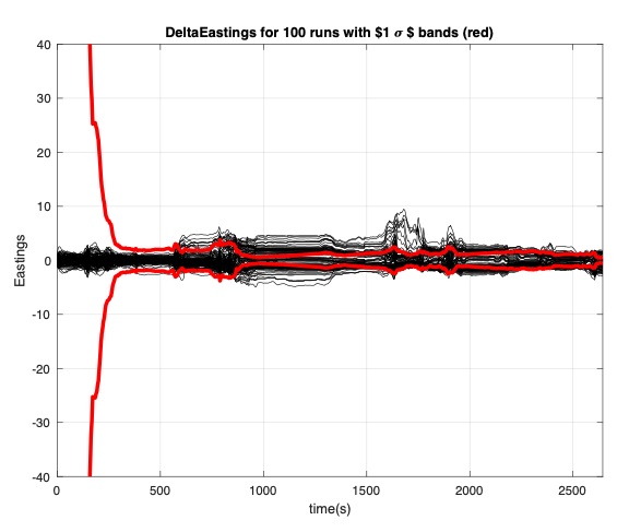
Fig 11: Eastings values minus the mean for 100 runs (black). Mean standard deviation bound (red)
To demonstrate the effect choosing different values of the noise parameters the TRN algorithm was run on sea trial data using an LRAUV using four different values of driftRate. Thes runs were done post dive 100 times each for driftRate values of 1%. 2%, 3% and 4% respectively. The percentrangeerror = 4% in all cases. The sonar beams used were the 4 beams of the onboard DVL.
The results are shown in Figure 12, Figure 13, Figure 14 and Figure 15. The standard deviations predicted by TRN along with the standard deviation of the 100 estimated trajectories is plotted vs. time for each case.
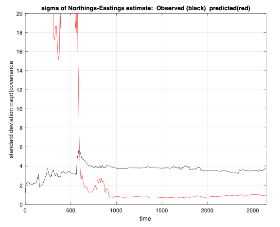
Fig 12: Standard deviation of NE position. Obaserved value (black). Predicted value (red). driftRate = 1%
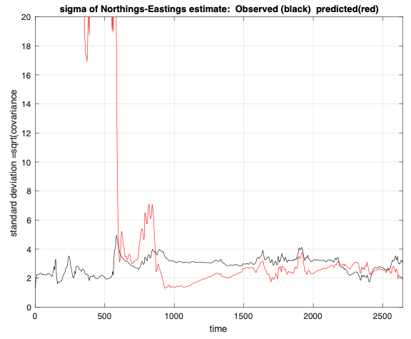
Fig 13: Standard deviation of NE position. Obaserved value (black). Predicted value (red). driftRate = 2%
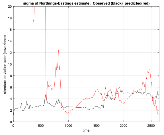
Fig 14: Standard deviation of NE position. Obaserved value (black). Predicted value (red). driftRate = 3%
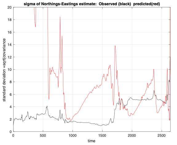
Fig 15: Standard deviation of NE position. Obaserved value (black). Predicted value (red). driftRate = 4%
Visible in the data is that the observed deviation of the width in trajectories (black line was approximately the same for all runs, but the value predicted by TRN depends on the user defined parameters. For the case driftRate = 1, it is clear that the predicted standard deviation is well below the observed value. It is also clear that for driftRate = 4, the predicted value is much larger. It is also evident that smaller values of the driftRate produce “tighter” converged solutions, even though the confidence in that solution is overly optimistic.
Choosing a driftRate = 2 would be a reasonable choice for this mission.
Choosing the number of beams
The examples presented above focused on the effect the two user defined parameters, driftRate and percentrange error, have on TRN performance. An additional degree of freedom in the system is the number of beams that are used in the measurement update. All of the above examples used the four beam lengths from the DVL (which also measured the vehicle’s velocity with respect to the seafloor). TRN can accept any number of beams. Clearly, using more beams offers more information. However, there are issues.
One obvious issue with increasing the number of beams is that beam ray tracing is computationally expensive and may affect the sample rate. Another issue is that TRN treats each beam as being completely uncorrelated from all the others. Any correlation results in information being “duplicated” with the result that the TRN filter will over converge, meaning that the estimates of the covariance uncertainties will be overly optimistic.
A common source of correlation is the beam soundings being too closely spaced. Overlapping of beam footprints is an obvious issue. Less obvious is that beam filtering techniques that use averages of beams adds correlation. Even less obvious is an assumption that the terrain is also assumed to be completely uncorrelated, meaning that knowing the terrain height at one location provides “no information” about the terrain height 1m away. The variations in real terrain do not meet this assumption, consequently larger spacing between beam soundings is good practice (a minimum of 3 or 4 meters has proven reasonable).
Choosing the noise and beam parameters
As described above, the user defined parameters that determine the performance of TRN are the driftRate, percentrangeerror and the number of beams. Often, these parameters are selected based on experience with using TRN at a site. For new missions, initial estimates can be obtained by testing multiple TRN configurations in simulation. Another option is to exploit the equivalence between a PF and an EKF. The advantage is that the EKF provides equations that provide insight into the sensitivity of algorithms performance with respect to parameter variations.
Sensitivity studies can be done using the EKF equations described in "Running TRN" below. A sample set of plots is presented in Figure 16, Figure 17 and Figure 18. Plotted are the standard deviations of the NED position as a function of the driftRate and percentrangeerror with 4 beams, 7 beams and 11beams. In each case the beams are pointed downwards in a cross-track configuration and are evenly spaced across a 90deg span. The standard deviation of the depth error for these plots was 0.5m. A trajectory at Portuguese Ledge as used as the baseline.
To generate these equations, the measurement matrix, H, was calculated along a nominal path in the terrain. Each element in H is the delta chance in beam length for a delta motion in either the Northings, Eastings or depth direction. Given H, the EKF covariance equations were iterated to steady-state at each time step.
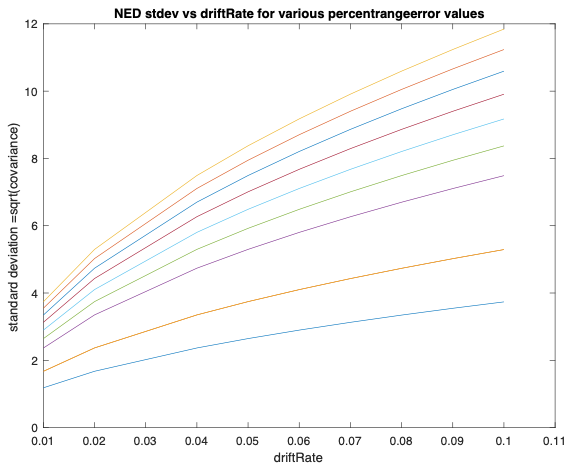
Fig 16: Predicted standard deviation of NE estimate using 4 besms.
percentrangeerror = [.01 .02 .02 .04 .05 .06 .07 .08 .09 .10]. MNM = 2
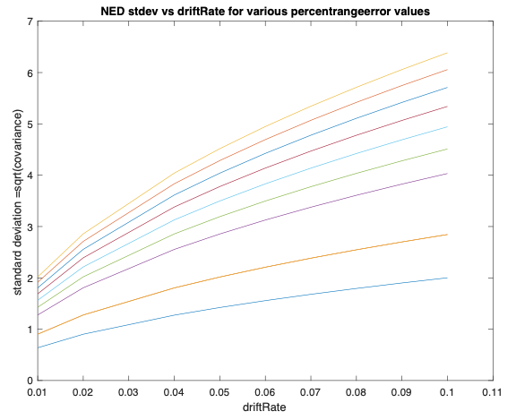
Fig 17: Predicted standard deviation of NE estimate using 7 besms.
percentrangeerror = [.01 .02 .02 .04 .05 .06 .07 .08 .09 .10]. MNN = 2
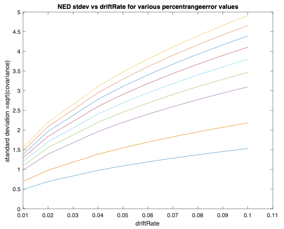
Fig 18: Predicted standard deviation of NE estimate using 11besms.
percentrangeerror = [.01 .02 .02 .04 .05 .06 .07 .08 .09 .10],. MNM = 2
Theory vs Practice and PF Modifications
An overview of how a particle filter works was described in "Summary of PF Operation". A detailed development is presented in Ref:Thrun, and its application to the AUV TRN problem is presented in Ref: Meduna. Presented here is a discussion of common practice for dealing with some issues that arise due to the difference between theory and practice when using a PF in the field. Also summarized are several additions to the basic PF algorithm that have been incorporated to improve its robustness.
The issues: unknown parameters, correlation and oblivious filters
The implicit assumption in any KF or EKF is that process noise (AHRS motion updates) and the measurement noise (beam lengths) are all zero mean Gaussian with known covariance and uncorrelated. It is also assumed and that all the parameters which define the measurements and equations of motion are known exactly. If these conditions are not met, the estimated values of NED and its covariance will be in error. Incorrect parameter values will bias the NED estimate. Correlated data will cause the filter to “over converge”, meaning that the estimate of uncertainty will be too tight. As stated above, this can cause a bad estimate of location to be accepted by the vehicle’s control system.
Clearly, it is unlikely that any fielded estimator will meet all these conditions.
Alignment biases (and other known types of sensor biases and drifts) will always exist. One “proper” way to deal with them is to include them as additional parameters to be identified along with the NED states of the system. Meduna provides examples of this for a wide range of sensor error in Ref:Meduna, but those capabilities have not been used in any field trials to date. One issue with augmenting the state vector is the computational cost. increasing the number of states greatly increases the number of particles required in a PF to maintain the same level of precision and may require reducing the number of particles used.
Correlation in the data will also exist and can be due to several potential sources. One is that measurements taken at one location can any information about the measurement taken at another location. Overlapping beam footprints are an obvious problem. A more subtle reason is that the terrain is assumed to be completely uncorrelated (completely random), which is not the case. Another source of correlation could be in how the beam data are filtered for noise and outliers. If a beam’s neighbors are used in the filtering, that is a potential source of correlation.
In practice, ensuring beam footprints are spaced at least 3 or 4 m apart in typical terrain helps reduce measurement correlation. Correlation can also be mitigated augmenting the state vector with coloring filters that describe the correlation (if it is known). Again, this results in an increase in the number of states.
A third issue when working with all types of Kalman filters is the “oblivious filter”. An oblivious filter exists when the process noise is too small. This causes the filter to assume that the process update is perfectly correct and hence measurements are no longer needed to correct the estimate. This can be a numerical issue.
Common practice in the field to deal with all these issues is to adjust the process noise artificially to achieve reasonable covariance values of the NED state estimate. If the unknown parameters are “small” and the correlation is not extreme this technique can work well.
Common practice: adjusting the process noise
Typically, the noise properties defined in the specification sheets for the sensors are “trusted” since they are often at least approximately correct. In the TRN code, the variable that defines the measurement noise is “percentrangeerror”. This is simply the assumed uncertainty in the beam length. It is implemented as a Gaussian covariance. A typical value is 4% of beam length.
The motion (process) noise is a different issue however. The disturbances acting on a system and the alignment of all the sensors are much more difficult to determine precisely. Further, they are often not Gaussian (e.g. alignment errors). Consequently, the process noise is often adjusted until credible covariances on the state (NED) estimates are achieved. (Adaptive process noise algorithms exist in the literature, but none is implemented in the current TRN algorithm.)
Two variables are used in the existing TRN code to describe process noise: the “driftRate” and the motion noise multiplier, “MNM”. driftRate is a bit of a misnomer. It is taken from the specification sheets for DVLs (e.g. 1% of distance travelled), but this is not a zero mean Gaussian error. This drift rate is typically associated with alignment errors and acts more like a bias in the motion.
In keeping with common practice, the TRN code approximates a Gaussian covariance to apply to the motion update which is large enough to account for the true motion uncertainty. The equation used in the TRN code is based on the circular error probability (CEP) calculations often used in projectile calculations. Here \(cep= driftRate * {\Delta}d\) and the standard deviation, \(\sigma\), is
\(\sigma = MNM * ({cep}\ /{\sqrt{-2*(log\ 1 - 0.5)}})\)
MNM is simply a convenient parameter used to adjust the amount of process noise in the calculations. It is currently defaulted to MNM = 2.
Note that other options for calculating the process noise standard deviation are available in the TRN code (e.g. a Gaussian noise added to a velocity input), but this formula has proven to be effective in previous field applications.
Additions for Robustness
In response to observed performance using TRN in the field, several additions to the algorithm have been incorporated to improve the algorithm’s robustness.
Normalized Innovations Sequence (NIS): It is possible for a PF to converge on a local minimum. When this occurs, the bounding box can tighten about the solution to the point that no particles are sampling the true location. To overcome this, the NIS logic was incorporated. This logic tests the innovations (difference between the measured and predicted beam lengths) for reasonableness. Specifically, it uses a chi-square test to determine the probability of observing a sequence of innovations. It the probability is low (e.g. less than 1%), it reinitializes the filter. See refHouts.
Alpha: TRN’s ability to produce an NED estimate depends on the information content of the terrain. If the terrain is flat, no information is present, but TRN may succeed in converging on a peak in the noise. To overcome this, an algorithm was introduced to reduce and broaden the PDF of the particle weights based on a measure of the variability in the terrain keeping the uncertainty of the estimate low. Alpha is the parameter that defines the reduction profile. See refDektor
Subsampling: For the baseline PF to function properly, ever beam from every particle must strike a point on the map. However, instances exist where the beam may land off the edge of the map or in a hole in the map. The subsampling algorithm was added to provide a proper calculation of the covariance update using only the subset of beams having valid measurements. See refStonestrom
Summary of EKF equations
where \(\frac{ \delta L_i}{\delta N}\) describes the change in \(i^{th}\) beam length for a small motion in the Northings direction, etc.
The process noise, \(\left[ \begin{array}{c} w_{\Delta N} \\ w_{\Delta E} \\ w_{\Delta D} \end{array} \right]_{n}\), is assumed to be zero mean, Gaussian with covariance
where \(\sigma_{\Delta D}\) is a constant (e.g. 0.5m and) \(\sigma_{\Delta N}\) and \(\sigma_{\Delta E}\) are computed from the Rayleigh distribution typically use in circular error probability (\(cep\)) calculations. Here \(cep\) is defined as \(cep = driftRate * \Delta d\) where \(\Delta d\) is the distance travelled in a time step, and MNM is the motion noise multiplier. The corresponding standard deviation is then
\(\sigma_{\Delta N} = MNM * (cep / \sqrt{(-2 * (log(1 - 0.5)))} \ )\)
The measurement noise, \(\left[ \begin{array}{c} v_1 \\ \bf{ .} \\ \bf{.} \\ v_m \end{array} \right]\), is assumed to be zero mean, Gaussian with covariance
where \(\sigma_{vi} = percentrangeerror * L_i\).
These equations can be written as
where the states, \(\bf{x}\), input, \(\bf{u}\) and output \(\bf{y}\) are
Given these equations, the basic operation of an EKF is an iteration between a process (or motion) update step and a measurement step. In the process update, the measured motions (u) are applied to the best estimate of the state (\(\hat{x})\) to yield an estimate of the state at the next time step (\(\bar{x}\)). An estimate of the covariance (i.e. uncertainty) of the state is updated from the current best estimate (P) to an estimate of what it will be at the next time step (M).
Process update
In the measurement update, the state estimate,\(\bar{x}\), is corrected using the measurement innovations, \(y- H \bar{ \bf{x} }_n\), to create the new best estimate of the state, \(\hat{x}\). The gain \(K\) determines how much the motion equations are to be trusted against the measurement equations. The gain \(K = P H^T {R_v}^{-1}\) is the optimal, time varying gain based on the noise parameters and is referred to as the Kalman gain. The prediction of the state covariance matrix, \(M\) is also updated to the new best estimate, \(P\), using the measurement information.
Measurement update
where \(K = P H^T {R_v}^{-1}\)
Note that this iterative process converges to a steady-state solution in which the amount of uncertainty introduced by the process noise is exactly offset by the information provided by the measurements.
TRN Quick Start Guide : libtrnav use and configuration
At it's core, TRN is relatively simple to use. The quick start guide takes you through the basic steps:
- Building libtrnav
- Creating a TRN instance
- Setting TRN configuration options
- Understanding TRN Parameters
- Providing TRN input : using PoseT and MeasT data structures
- Interpreting TRN output (position estimates)
An example application, trn-player, is included.
Contents
- TRN Quick Start Guide : libtrnav use and configuration
Building libtrnav
Dependencies
- libnetcdf
- mframe (MBARI internal repo, git@bitbucket.org:mbari/mframe.git)
- libpthread
- libm
- libcurl (for some versions of NetCDF)
- libhdf5 (for some versions of NetCDF)
- librt (some linux builds)
libtrnav may be built with either cmake or gnu make. cmake is the preferred build system.
In the following sections the following convention is used:
- $TRN_BUILD : directory containing libtrnav (and mframe) repo(s)
- $LIBTRNAV : path to the libtrnav repo
- $MFRAME : path to the mframe repo
- $SANDBOX : path to directory containing libtrnav installation and libtrnav-data
These environment variables are used only to create a consistent frame of reference in the documentation and examples; they are not required for TRN or referenced by any of the software.
Build Sandboxed Installation for trn-player Example
libtrnav includes a script, opt/examples/trn-player/pkg/trnplayer-sandbox.sh that generates a sandboxed build for the trn-player example:
$LIBTRNAV/opt/examples/trn-player/pkg/trnplayer-sandbox.sh -v
The script is also available in the Appendices.
creates directory trnplayer-<id> (TRN_BUILD) containing the sandbox directory (SANDBOX). If the -k option is used, the libtrnav and mframe directories are preserved; otherwise, they are deleted from trnplayer-<id>.
Alternatively, mframe and libtrnav may be built manually (installed to trnplayer/sandbox) as follows:
# create TRN_BUILD directory, go there
mkdir trnplayer
cd trnplayer
export TRN_BUILD=$PWD

# build mframe
cd $TRN_BUILD
git clone git@bitbucket.org:mbari/mframe.git
cd mframe
mkdir build
cd build
cmake -DCMAKE_INSTALL_PREFIX=$PWD/pkg ..
cmake --build .
cmake --install .

# build libtrnav, install to TRN_BUILD/sandbox
cd $TRN_BUILD
git clone git@bitbucket.org:mbari/libtrnav.git
cd libtrnav
mkdir build
cmake -DCMAKE_INSTALL_PREFIX=$TRN_BUILD/sandbox ..
cmake --build .
cmake --install .

# set SANDBOX environment variable
cd $TRN_BUILD/sandbox
export SANDBOX=$PWD

# install libtrnav-data (optional, to run trn-player examples)
cd $SANDBOX
git clone git@bitbucket.org:mbari/libtrnav-data.git
General Build and Installation
It is recommended to build libtrnav using cmake. The general build instruction are similar to the sandboxed example, except that libtrnav is installed to the default location (/usr/local) or another directory:
# build libtrnav
cd $TRN_BUILD
git clone git@bitbucket.org:mbari/libtrnav.git
cd libtrnav
mkdir build
cmake ..
cmake --build .
cmake --install .
Use option -DCMAKE_INSTALL_PREFIX=<path> when configuring libtrnav to install to another directory (e.g. as in the sandboxed build).
All cmake build output goes to the build directory.
If mframe is not installed to one of the default locations:
- /usr/local
- TRN_BUILD/mframe/build/pkg
the MFRAME_PKG option must be specified when building libtrnav :
cmake -DMFRAME_PKG_PATH=<path> [options...] ..
cmake build options
cmake options include
buildOptROV=ON|OFF     Enable build of opt/rov libraries and applications
buildTrnNoRand=ON|OFF  Disable TRN random seed generation
buildTrnLog=ON|OFF     Disable binary TRN log
buildTrnLogEst=ON|OFF  Disable binary TRN estimate log
buildTrnCEPCorr=ON|OFF Enable CEP correction (deprecated, don't use)
enable during cmake configuring using
cmake -D<option>=<value>...
The install path for cmake may be configured using
cmake -DCMAKE_INSTALL_PREFIX=<path>...
or during install using
cmake --install . --prefix=\<path\>
In both cases, the install path should be absolute.
Build with gnu make (deprecated)
The core libraries are built using
make
sudo make install
components that require libmframe are built with the trnc target.
make trnc
for a full list of targets (including application-specific), use
make help
The install path for gnu make is generally set using the environment variable PREFIX. The environment variable DESTDIR may also be used for greater flexibility:
${DESTDIR}${PREFIX}/...
Note that DESTDIR should include a trailing slash, PREFIX should not.
gnu make output goes to the libtranav/bin and libtrnav/build. The build directory contains intermediate files, bin contains libraries and executables.
tar.gz distribution
The top level Makefile includes a dist target that builds a tar.gz distribution, libtrnav-\<version>.tar.gz
The opt/sentry directory includes a script for packaging libtrnav and libmframe, along with scripting to configure and install them using either cmake or gnu make. This is used to distribute libtrnav for the WHOI Sentry vehicle. This is a convenient way to distribute the code and build stand-alone installations in a test directory.
Details are provided in opt/sentry/README-trndev-build.md.
Build Doxygen doc
The libtrnav doc directory contains a Doxygen configuration file; while the code does not consistently include doxygen markup, Doxygen generates a fairly sensible package that is convenient to navigate. It may be built using the gnu make doc target:
make doc
Output will be written to doc/doxygen.out
libtrnav Contents
See the Software Guide for a list of libtrnav applications and libraries.
Creating a TRN instance
The C++ API has a number of constructors with different configuration information, for example:
// minimal constructors
TerrainNav();

// commonly used
TerrainNav(char *mapName, char *vehicleSpecs,
             const int &filterType, const int &mapType);

TerrainNav(char *mapName, char *vehicleSpecs,
             const int &filterType, const int &mapType, char *directory);

TerrainNav(char* mapName, char* vehicleSpecs, char* particles,
             const int& filterType, const int& mapType, char* directory);
The C API constructor takes a trn_cfg_t structure. The structure members are used to invoke a C++ constructor.
wtnav_t *wtnav_new(trn_cfg_t *cfg);
The C++ TRN constructor arguments are described in the following section.
In the quick start section, we'll reference the C++ API; the basic steps are similar for the C API, in which the trn_cfg_t structure replaces the constructor arguments.
It's worth noting that TRN may be run as a TCP/IP server using the trn-server application. trn-server enables applications to perform TRN functions via TCP using TrnClient (or it's base class TerrainNavClient). trn-server configuration is essentially the same as for a TRN instance constructed in an application.
Configuring TRN
Consider the parameters passed to the TRN C++ constructor, summarized in the following table and explained below.
| Parameter | Description | ||||
|---|---|---|---|---|---|
| mapName | map file name; format should match type specified by mapType argument (path is specified using TRN_MAPFILES environment variable) |
||||
| vehicleSpecs | Vehicle specs file name; contents defined below (path is specified using TRN_CONFIGDIR environment variable) |
||||
| filterType | An integer (enumeration) indicating a TRN filter variant. While several experiment filter types exist, filter type 2 (TRN_FT_PARTICLE, a particle filter) is used almost exclusively. | ||||
| mapType | An integer (enumeration) indicating a TRN map format:
| ||||
| directory | directory in which to save TRN logs and store copies of config files | ||||
| particles | particle file name (logs particle file information; optional (a lot of data) |
Applications typically use a configuration file and environment variables to obtain values used to construct TerrainNav and/or initialize utility classes TNavConfig or TrnAttr that are used to manage configuration values. TrnAttr is used to parse and use key/value pairs primarily used for terrainAid.cfg.

Fig: TRN configuration
The map files, configuration files, and environment variables are described in greater detail in the following sections.
Application Configuration Files
There are three files strictly required to configure TRN:
| File | Description |
|---|---|
| Map file | Contains TRN map data in one of two supported formats |
| Vehicle specification file | Enumerates bathymetry sensors used by TRN and describes mounting geometry |
| Sensor specification file(s) | Describes sensor beam geometry and other TRN parameters referenced by the vehicle specification file. |
The format and content of these is described below.
Though each application is different, most use a configuration file and environment variables to specify TRN configuration parameters, though it is not strictly required.
terrainAid.cfg
Some applications use a file called terrainAid.cfg to load configuration values; it is convenient, but not required. The trn-player example app also includes a configuration file parser that supports terrainAid.cfg syntax.
terrainAid.cfg is a text file with key/value entries using the format:
// comment...
key = value;
Commonly used parameters include:
| Parameter | Description |
|---|---|
| mapFileName | map file name (path specified by TRN_MAPFILES) |
| map_type | Numeric map type value (1: DEM/GRD 2: BO) |
| vehicleCfgName | vehicle specification file |
| resonCfgName | Reson multibeam sonar sensor specification |
| dvlCfgName | DVL sensor specification file |
| filterType | type of TRN filter (usually 2: particle filter) |
| terrainNavServer | TRN server IP address applies only to trn-server (TRN via TCP/IP) |
| terrainNavServer | TRN server IP port applies only to trn-server (TRN via TCP/IP) |
| allowFilterReinits | enable TRN filter reinitialization if true |
These values are used primarily by the replay application (libtrnav/opt/dorado):
| Parameter | Description |
|---|---|
| samplePeriod | for DVL, used to skip lines with timestamps inside previous sample |
| useMbTrnData | Use the MbTrn data format (MbTrn.log) if true, otherwise use TerrainAid.log |
| lrauvDvlFilename | use lrauv log data |
| useIDTData | use Imagenex DeltaT data |
| maxNorthingCov | convergence criteria |
| maxEastingCov | convergence criteriay |
| maxNorthingError | convergence criteriay |
| maxEastingError | convergence criteria |
Other parameters that are experimental or used for debug may generally be excluded or commented out; these include
| Parameter | Description |
|---|---|
| particlesName | name of particles file (logs particle state information). IO/storage intensive; generally for debugging |
| useModifiedWeighting | select one of several alternative particle weighting schemes. |
| forceLowGradeFilter | deprecated? |
In practice, applications like replay populate a (singleton) TNavConfig instance or TrnAttr using the contents of a configuration file. The TrnAttr struct contains a set of elements associated with terrainAid.cfg, a config file used by Dorado and some other applications. The TrnClient uses TrnAttr, and replay has code for parsing terrainAid.cfg into TRN_attr. TrnAttr should be used for new applications that use terrainAid.cfg keys.
In contrast, the TrnPlayer example in the Quick Start Guide does not require a configuration file. It uses the TrnPlayerCtx to parse options passed on the command line. The context class contains configuration values and instance variables. This pattern helps to support multiple instances concurrently. TrnPlayer does support an extended terrainAid.cfg syntax, and TrnPlayerCtx includes parsing code.
The ROV TRN implementation (libtrnav/opt/rov) uses a similar context base approach; it's trnxpp_ctx context class supports both command line and configuration files.
Environment Variables
Several environment variables may be used to set the paths file arguments, though it is not required by TRN per se. This is done to enable use cases in which TRN configuration parameters are passed remotely, e.g. to a TRN server instance, whose host environment may differ from the callers.
Core Environment variables are summarized in the following table; additional variables are described in later sections.
| Environment | Description |
|---|---|
| TRN_LOGFILES | Output directory for TRN logs and config file copies |
| TRN_DATAFILES | Input directory for TRN config files (e.g. vehicle specs, sensor specs) |
| TRN_MAPFILES | Path to TRN map files |
Map Files
As indicated above, TRN supports two map file formats: digital elevation maps (.GRD) or binary octree files. Binary octrees are typically used, and though a single monolithic map file may be used, they are often sub-divided into smaller tiles that reduce memory use. Tools exist in the libtrnav repository to generate tiled GRD and BO maps.
When tiled maps are used, they must be stored in the same directory, along with a tiles.csv file defining the tile boundaries.
The name of the map directory or single map file is passed to the TRN constructor, and the TRN_MAPFILES environment variable set accordingly.
Vehicle and Sensor Spec Files
There are two types of configuration files associated with libtrnav: the vehicle specification file and one or more sensor specification files. These are required by TRN.
The vehicle spec file specify some TRN parameters, and enumerates the sensors that will be used by TRN, and describes mounting orientation. Each of the sensors is defined in a separate sensor spec file, and defines additional sensor-specific TRN parameters, e.g. beam geometry. These are described in detail below, with examples.
With these files, TRN supports processing bathymetry (beams) from several types of commonly used sensors - e.g. DVLs and multibeam sonars; the parameters they describe are primarily about describing the sensor geometry and orientation with respect to the platform. TRN is able to apply the appropriate geometry calculations to bathymetry inputs for the given navigation and attitude.
There are use cases that don't fit typical fixed sensors, for example, in a system in which a bathymetry sensor is on a rotating platform, the mounting angles change dynamically. In such cases, the application may set the relevant configuration file parameters to zero, and geometry calculations for TRN inputs will need to be computed by the application.
Vehicle Specification File
The vehicle specification file is a text file containing a list of sensor config files, sensor mounting geometries, and a process noise parameter. It's format is rigid; it uses a naming convention <NAME>_spec.cfg, and its contents are arranged as follows:
# comments...

NAME:<config file name (w/o _spec.cfg)>
NUMSENSORS:<number of sensor entries (integer)>
DRIFTRATE:<process noise figure (floating point)>

SENSORNAME:<sensor spec file name (w/o _spec.cfg)>
DR:<phi>,<theta>,<psi>
DT:<x>,<y>,<z>
...
Example: Vehicle Spec File
# Vehicle specification sheet
#----------------------------
NAME:mappingAUV
NUMSENSORS:3
DRIFTRATE:1.5

SENSORNAME:rdiDVL
DR:0,0,0
DT:0,0,0

SENSORNAME:resonSeabat8101
DR:0,0,0
DT:0,0,0

SENSORNAME:imagenexdeltat
DR:0,0,0
DT:0,0,0
The parameters are described as follows:
| Name | Description/th> |
|---|---|
| NAME | Configuration name (matches file name, w/o _spec.cfg suffix) |
| NUMSENSORS | Number of sensor entries to follow |
| DRIFTRATE | Somewhat of a misnomer, represents TRN process noise, typically 1.5/2 depends on terrain, instruments, etc. |
| SENSORNAME | name of sensor spec file (w/o _spec.cfg suffix) |
| DR | sensor orientation, NED Euler angles in vehicle frame (degrees) |
| DT | sensor mounting location, distance from vehicle cente (meters) |
Mounting geometry parameters DR and DT describe the location and orientation of the sensor with respect to the origin in the vehicle frame of references; typically this is X/FWD, Y/STBD, Z/DOWN, i.e. NED.
DT is the XYZ distance from the vehicle center, in meters. DR are NED Euler angles (phi, theta, psi) with respect to FWD, STBD, DOWN.
Sensor Specification File
The sensor specification files, referenced by the vehicle spec file, are text files containing a bathymetry sensor configuration information. A number of different sensors are supported. It's format is rigid; it uses a naming convention <NAME>_spec.cfg, and their contents are arranged as follows:
# comments...
NAME:<sensor name (matches file, w/o _spec.cfg suffix)>
TYPE: <sensor type (integer)>
NUMBEAMS: <number of beams>
PERCENTRANGEERROR: <range error, %>
BEAMWIDTH: <beam width (deprecated)>

# optional fields, type-dependent
PITCH ANGLES:<comma separated list of pitch angles>
DELTA_PITCH:<pitch angle increment>
INIT_YAW ANGLE:<comma separated list of yaw angles>
DELTA_YAW: <yaw angle increment>
INIT_PITCH ANGLES|starting pitch angle(s) in sensor frame, decimal degrees|
| Name | Description | ||||||||||||
|---|---|---|---|---|---|---|---|---|---|---|---|---|---|
| NAME | Configuration name (matches file name, w/o _spec.cfg suffix) | ||||||||||||
| TYPE | Sensor type enumeration value
| ||||||||||||
| NUMBEAMS | number of beams | ||||||||||||
| PERCENTRANGEERROR | estimated range error (% of range) | ||||||||||||
| BEAMWIDTH | width of beams, m (deprecated) | ||||||||||||
| PITCH ANGLES | sensor beam geometry: pitch angles in sensor frame, decimal degrees used for non-multibeam types |
||||||||||||
| DELTA_PITCH | sensor beam geometry: pitch angle increment, decimal degrees used for non-multibeam types |
||||||||||||
| YAW ANGLES | sensor beam geometry: yaw angles in sensor frame, decimal degrees used for non-multibeam type |
||||||||||||
| DELTA_YAW | sensor beam geometry:yaw angle increment, decimal degrees used for non-multibeam types |
The sensor beam geometry parameters assume that bathymetry sensors have beams that arranged in an angular or radial array at uniform angular intervals, which is true of all currently used TRN sensors.
Multibeam sensors are assumed to extend radially from the sensor origin, i.e. subtending an arc with a specified swath angle, typically 90-120 degrees.
Non-multibeam sensors (e.g. DVLs) are assumed to be arranged in a radial array around the sensor origin, with azimuth YAW ANGLE (relative to E) separated by DELTA_YAW. The beams are pitched downward at PITCH ANGLE, optionally incrementing by DELTA_PITCH. DVLs typically have 4 beams, separated by 90 degrees, oriented at an outward angle with respect to vertical.
For both types of sensors,
Example: multibeam sensor spec file
# Sensor specification sheet
#----------------------------
NAME: resonSeabat8101
TYPE: 2
NUMBEAMS: 20
PERCENTRANGEERROR: 4
BEAMWIDTH: 1.5

PITCH ANGLES: 0
DELTA_PITCH: 0
INIT_YAW ANGLE: 0
DELTA_YAW: 0
Example: DVL sensor spec file
# Sensor specification sheet
#----------------------------
NAME: rdiDVL
TYPE: 1
NUMBEAMS: 4
PERCENTRANGEERROR: 4
BEAMWIDTH: 3.9

PITCH ANGLES:30, 30, 30, 30
YAW ANGLES: -45, 135, 45, -135

#----------------------------------------------------------------
# Sensor beam configuration diagram:
#
# Beam numbering convention, looking down on Dvl from above.
# x and y are the vehicle axes. x points to port, y to starboard.
#
#                  x
#                  ^
#                  |
#                1 | 3
#                  |------> y
#                4   2
#
# Each beam is spaced 45 degrees from the horizontal/vertical.
# The inclination angle is 30 degrees.
Relevant files in the repository include:
terrain-nav/TerrainNav.h,cpp
terrain-nav/structDefs.h
trnw/trn_msg.h
Other TRN Configuration: run-time and compilation options
To recap, we've looked at TRN inputs and parameters required to create a TRN instance:
- configuration file (e.g. terrainAid.cfg)
- map file
- vehicle spec file
- Number of sensors
- Navigation drift rate
- Bathymetry sensor specification list and mounting geometry
- sensor spec file(s)
- sensor name and type
- estimated range error
- beam geometry
Run time TRN Configuration
The following table summarizes TRN parameters that may be set at run-time:
| Parameter | File | Description |
|---|---|---|
| setVehicleDriftRate(double &driftRate) | terrain-nav/TerrainNav.h |
Sets the vehicle inertial drift rate parameter. The driftRate parameter is given in units of % drift in meters/sec. Default : value in vehicle specification sheet. |
| setFilterReinit(bool allow) | terrain-nav/TerrainNav.h | Enable TRN filter reinitialization. Default: false |
| void setEstNavOffset(double offset_x, double offset_y, double offset_z) | terrain-nav/TerrainNav.h | This function sets the x, y, z values of the estNavOffset structure that holds the prior offset estimate. This function is used prior to a particle filter reinit callvin order to force the reinit to be centered on a particular offset value rather than the actual last offset estimate. This capability was created for use by the MB-System program mbtrnpp so that reinit could, if necessary, be forced to be centered on a zero offset or a prior very good offset estimate if that is known. Resetting the prior offset estimate addresses the occasional tendency of TRN to converge on similar topoography far from the actual location - when this occurs convergence will soon be lost, but the reinit should be centered on a more likely position if that is known external to TRN. |
| setInitStdDevXYZ(double sdev_x, double sdev_y, double sdev_z) | terrain-nav/TerrainNav.h | Values potentially used in reinitFilter and estimatePose Replaces _initVars member variable, use NULL to reset to defaults Using the method except immediately before filter reinitialization (i.e. on a running filter) may give undefined output. |
Compile time options
In addition, there are a number of TRN parameters that may be set when compiling libtrnav, described in the table below. This list is not comprehensive; the code contains a number of parameters introduced over time to try out experimental features for research; these are generally disabled and should remain so. Note that these are rarely modified; change only if you know what you are doing.
| Parameter | File | Description |
|---|---|---|
| TRN_MAX_BEAMS | terrain-nav/structDefs.h | Maximum number of bathymetry beams Default: 120 |
| TRN_MSG_SIZE | terrain-nav/structDefs.h | Maximum TRN server (commsT) message length (bytes) Default: 8000 |
| N_COVAR | terrain-nav/structDefs.h | covariance matrix size for TRN estimates Default: 45 |
| MAX_PARTICLES | particleFilterDefs.h | maximum number of particles; note this has a potentially large impact on computational load and TRN performance Default: 10000 |
| MAX_NIS_VALUE | terrain-nav/TerrainNav.h | Maximum allowable NIS Windowed Average (used by TerrainNav) Default: 1.4 |
| NIS_WINDOW_LENGTH | terrain-nav/genFilterDefs.h | Length of NIS window (used by filter) Default: 29 |
| MAX_RANGE | terrain-nav/genFilterDefs.h | Maximum allowable sonar range Default: 220 |
| MAP_NOISE_MULTIPLIER | terrain-nav/genFilterDefs.h | Multiplier on map noise in particle filter should be 1.0 usually |
| MOTION_NOISE_MULTIPLIER | terrain-nav/genFilterDefs.h | Multiplier on motion noise stdev in particle filter should be 2.0 usually |
| [XYZ]_STDDEV_INIT | terrain-nav/genFilterDefs.h | FILTER INITIALIZATION PARAMETERS
[XYZ]_STDDEV_INIT values establish a map search area; values have units of meters, and are application-specific.
If the distribution is uniform, these comprise a box (see initDistribType, TNavFilter.h).
If set incorrectly, TRN may fail to initialize correctly, resulting in errors, e.g. TerrainNav::Filter not initialized - vehicle is currently within a non-valid region of the reference map TerrainNav::Cannot compute pose estimate; motion has not been initialized. Typical values include: [XY]_STDDEV_INIT 60.0 Portuguese Ledge/Dorado 600.0 Axial/Sentry [Z]_STDDEV_INIT 5.0 Portuguese Ledge/Dorado, Axial/Sentry 10.0 ? |
Providing TRN Input: PoseT, MeasT
Once a TRN instance is configured, it is provided with bathymetry and navigation inputs that it uses to update the particle filter state. Updates are periodically passed to TrN using in an appropriate data structure (poseT, measT) via TRN's input methods: motionUpdate and measUpdate.

Fig: TRN cycle
motionUpdate is used to update vehicle navigation and attitude information. It requiers a poseT structure, and must be called first; calls made to measUpdate before motionUpdate has successfully completed will fail.
measUpdate is used to provide bathymetry at a specified location and attitude to TRN, and requires a measT structure and sensor type.
estimatePose accepts a poseT reference and an estimate type. It returns the current TRN position estimate of the specified type along uncertainties (array of covariances).
The C++ API calls are as follows:
void TerrainNav::motionUpdate(poseT* incomingNav)
void TerrainNav::measUpdate(measT* incomingMeas, const int& type)
void TerrainNav::estimatePose(poseT* estimate, const int &type)
PoseT and MeasT are defined in terrain-nav/structDefs.h.
The C API uses wmeast_t and wposet_t, which are thin C wrappers around PoseT and MeasT objects. wposet_t and wmeast_t are defined in trnw/trnw.h
poseT
The PoseT structure is used for both input and output to TRN.
For input (motionUpdate), most applications populate only a subset of these fields for input:
| Parameter | Description |
|---|---|
| time | Time in posix epoch seconds (seconds since 1970-01-01T00:00:00) |
| x,y,z | bathymetry sensor origin, world frame (e.g. UTM) (meters) |
| vx,vy,vz | velocity in x,y,z direction (m/s) |
| phi,theta,psi | vehicle pitch, roll, heading, world frame (radians) |
| dvlValid | true if DVL input is valid |
| gpsValid | true if GPS input is valid |
| bottomLock | true if DVL has bottom lock |
vx is strictly required for TRN input; vy, vz are optional. The complete structure is shown below.
To fully initialize, TRN requires that a motion update be received with vx (along-track velocity) not equal to zero, which indicates forward motion. Until that happens, TRN emits an error message indicating that TRN has not been initialized when measurement updates are received. Once motion has been established, motion and measurement updates may occur in any order.
vx is used for most configurations to indicate motion, and its value is not critical, but must be != 0 in order for TRN to initialize.
In general, TRN does not require velocity to operate, but in some contexts, velocity may be integrated to determine position, in which case it is needed.
For output (estimatePose), a PoseT instance is passed into estimatePose, which populates these fields:
| Parameter | Description | ||||||||||
|---|---|---|---|---|---|---|---|---|---|---|---|
| time | Time in posix epoch seconds (seconds since 1970-01-01T00:00:00) | ||||||||||
| x,y,z | position estimate, world frame (e.g. UTM) (meters) | ||||||||||
| covariance | position estimate uncertainty array:
|
The remaining fields are somewhat application-specific, and may be used in some TRN configurations. The complete poseT structure appears below.
struct poseT {

    double x, y, z;                // North, East, Down position (m)
    double vx, vy, vz, ve;         // Vehicle velocity wrto terrain (m/s) [1]
    double vw_x, vw_y, vw_z;       // Vehicle velocity wrto water (m/s) [1]
    double vn_x, vn_y, vn_z;       // Vehicle velocity wrto an inertial frame (m/s) [1]
    double wx, wy, wz;             // Vehicle angular velocity wrto an inertial frame (rad/s) [1]
    double ax, ay, az;             // Vehicle aceleration wrto an inertial frame (m/s^2) [1]
    double phi, theta, psi;        // 3-2-1 Euler angles relating Body frame to
                                   // an inertial NED frame (rad).
    double psi_berg, psi_dot_berg; // TRN states

    double time;                   // Time (seconds since 01-01-1970T00:00:00)

    bool dvlValid;                 // DVL measurement valid flag
    bool gpsValid;                 // GPS measurement valid flag
    bool bottomLock;               // DVL bottom lock valid flag

    double covariance[N_COVAR];    // Covariances: XYZ, phi, theta, psi, wy, wz
                                   // (passively stable in roll) (see above units)

    // [1] coordinates in Body Frame

    poseT();
    poseT& operator=(const poseT& rhs);
    poseT& operator-=(const poseT& rhs);
    poseT& operator+=(const poseT& rhs);

    int   serialize(char *buf, int buflen);
    int unserialize(char *buf, int buflen);
};
measT
The measT structure is used for measurement update (bathymetry) input. In libtrnav, measurements are often referred to as beams; this stems from the fact that TRN bathymetry sensors are historically acoustic instruments, i.e. sonars and DVLs. They could, however, include LIDAR or other sensors. Here, measurement and beams are used interchangeably.
struct measT {
    double time;              // Measurement time (s)
    int dataType;             // Sensor type [1]
    double phi, theta, psi;   // 3-2-1 Euler angles relating Body frame to
                              // an inertial NED frame (rad).
    double x, y, z;           // North, East, Down position (m)

    double* covariance;       // covariance array [2]
    double* ranges;           // beam ranges [2]
    double* crossTrack;       // beam component perpendiclar to velocity [2]
    double* alongTrack;       // beam component parallel to velocity [2]
    double* altitudes;        // beam component downward [2]
    double* alphas;           // alpha values [2]
    bool* measStatus;         // beam measurement valid flag [2]
    unsigned int ping_number; // measurement number
    int numMeas;              // number of beams
    int* beamNums;            // beam numbers (for sensors w/ variable beams) [2]

    // [1] sensor type enumerations
    //      1: DVL
    //      2: Multibeam
    //      3: Single Beam
    //      4: Homer Relative Measurement
    //      5: Imagenex multibeam
    //      6: Side-looking DVL
    // [2] array with dimension numMeas

    measT();
    measT(unsigned int nummeas, int datatype);
    ~measT();
    void clean();
    measT& operator=(const measT& rhs);

    int   serialize(char *buf, int buflen);
    int unserialize(char *buf, int buflen);
};
On input, measT is passed into measUpdate, with these fields populated:
| Parameter | Description | ||||||||||||
|---|---|---|---|---|---|---|---|---|---|---|---|---|---|
| time | Time in posix epoch seconds (seconds since 1970-01-01T00:00:00) | ||||||||||||
| time | Time in posix epoch seconds (seconds since 1970-01-01T00:00:00) | ||||||||||||
| x,y,z | bathymetry sensor origin, world frame (e.g. UTM) (meters) | ||||||||||||
| phi,theta,psi | vehicle pitch, roll, heading, world frame (radians) | ||||||||||||
| dataType | sensor type
|
||||||||||||
| ranges | Beam range (length) array (meters) | ||||||||||||
| numMeas | number of beams (size of arrays ranges, crossTrack, etc.) | ||||||||||||
| crossTrack | beam range component perpindicular to direction or travel (m) | ||||||||||||
| alongTrack | beam range component in direction or travel (m) | ||||||||||||
| altitudes | beam range component down (m) | ||||||||||||
| measStatus | beam valid flag array (true if valid) | ||||||||||||
| ping_number_ | Bathymetry measurement sequence number (assumed to increase monotonically, > 0) | ||||||||||||
| beamNums | Beam numbers of ranges and components |
To recap, the TRN computation cycle is shown again below, in which TRN is provided with periodic motion and measurement updates (in that order), followed by a call to estimatePose to request a position estimate with uncertainties.
Fig: TRN cycle
The call to estimatePose requires a poseT (to contain the return value), and a measurement type:
void estimatePose(poseT* estimate, const int &type);
The measurement type argument is described below; in general, the MMSE value is used.
| Type | Description |
|---|---|
| 1: MLE | Maximum Likelihood Estimator, which maximizes the probability of observed data |
| 2: MMSE | minimum mean square error, which minimizes the expected squared difference between the estimated value and the true value |
In other words, MLE is more a peak (best single match), which is potentially an incorrect local maximum. MSE is the best/closest, across the range of estimates.
The covariance array returned has N_COVAR elements, the most commonly used of which are:
| Index | Description |
|---|---|
| 0 | x/N covariance |
| 2 | y/E covariance |
| 5 | z/D covariance |
| 1 | XY covariance |
Input streams may be decimated (sub-sampled) as needed. Sensor data streams are typically at different rates. Bathymetry inputs should correspond to the location and attitude associated with them. If data are buffered, be aware that updates should not use data that is too old, or for which there is significant temporal skew between motion and measurement updates.
Example TRN application: trn-player
A reference TRN application called trn-player is included in the libtrnav repository (libtrnav/opt/examples/trn-player).
trn-player provides a minimal demonstration of TRN:
- Configures a TRN instance
- Reads bathymetry, navigation, and attitude data from a log file
- Passes poseT and measT data structures to motionUpdate and measUpdate
- Calls estimatePose and sends TRN output to the console in CSV format (convenient for plotting), and to log files.
The contents are as follows:
| File | Description |
|---|---|
|
opt/examples/trn-player/TrnPlayer.hpp,h opt/examples/trn-player/TrnPlayer.cpp,h opt/examples/trn-player/TrnPlayerCtx.hpp,h opt/examples/trn-player/trn-player.cpp,h terrain-nav/TerrainNav.cpp,h |
trn-player source code |
| opt/examples/trn-player/pkg/trnplayer-sandbox.sh | generates sandboxed build for trn-player example |
Data and configuration files may be obtained from the libtrnav-data repository: https://bitbucket.org/mbari/libtrnav-data
| File | Description |
|---|---|
|
libtrnav-data/trn-player/data/csv libtrnav-data/trn-player/data/mbtrn libtrnav-data/trn-player/data/tnav |
TRN configuration files and data using different log formats. |
| libtrnav-data/trn-player/maps/PortTiles | Binary octree map |
| libtrnav-data/trn-player/trnplayer.cfg | trn-player configuration file |
The trn-player example builds with libtrnav; see build instructions above and/or use the trnplayer-sandbox.sh script to build the sandboxed version used below.
In this example, the following conventions are used:
- $TRN_BUILD : directory containing libtrnav (and mframe) repo(s)
- $LIBTRNAV : path to the libtrnav repo
- $MFRAME : path to the mframe repo
- $SANDBOX : path to directory containing libtrnav installation and libtrnav-data
These environment variables are used only to create a consistent frame of reference in the documentation and examples; they are not required for TRN or referenced by any of the software.
Running trn-player
These instructions show how to use trn-player using sample data that is available in the libtrnav-data repo. This example shows how to run mbtrn, one of several sets in libtrnav-data.
Clone the sample data repo into the $SANDBOX directory, if you haven't already done so:
cd $SANDBOX
git clone git@bitbucket.org:mbari/libtrnav-data.git
The $SANDBOX directory should contain:
bin
include
lib
share
libtrnav-data
Run TRN player using the example configuration file included with libtrnav-data:
cd $SANDBOX

# run trn-player using default settings and verbose output
./bin/trn-player --config=libtrnav-data/trn-player/trnplayer.cfg -v

# for help and other options use
./bin/trn-player -h
The default used above runs a data set from an MbTrn.log; the sample data also includes data from TerrainNav.log, TerrainAid.log, and CSV files (DVL, IDT, and multibeam formats).
To run other other data sets from the example config file, edit the config file, commenting out all but the selected configuration, then run again as above.
To process your own data, use the example configuration file and config file reference ($LIBTRNAV/sandbox/share/README-config.md) to create a new configuration file that references your data, maps, and configuration files, then run as above.
The trn-player default location for maps and data are ./maps and ./data; configuration files are assumed to be located in the data directory. the -c option specifies the config directory.
Alternatively, these methods may be used to reference trn-player inputs:
# Option 1: use data and map symlinks
Make symbolic links to the sample data maps and data:

ln -s libtrnav-data/trn-player/data/mbtrn data
ln -s libtrnav-data/trn-player/maps maps

# Option 2: use the trn-player options to set
# config (-c), data (-d), and map (-m) directories:

-c "libtrnav-data/trn-player/data/mbtrn"
-d "libtrnav-data/trn-player/data/mbtrn"
-m "libtrnav-data/trn-player/maps"

# Option 3: copy/rename the map, data directories to your directory

cp -R libtrnav-data/trn-player/maps maps
cp -R libtrnav-data/trn-player/data/mbtrn data
Example: process tnav example data without configuration files
The example data set in libtrnav-data/trn-player/tnav uses the TerrainNav.log and has a different vehicle specs file; if configuration file is not used, options must be passed on the command line to configure trn-player.
Using command line options only:
cd $SANDBOX

./bin/trn-player \
-d "libtrnav-data/trn-player/data/tnav" \
-c "libtrnav-data/trn-player/data/tnav" \
-m "libtrnav-data/trn-player/maps" \
-V "RDIequippedAUV_specs.cfg" \
-s 1 -l 1 -F -v

# -V : vehicle specs file name
# -s : sensor type DVL
# -l : log type TerrainNav.log
# -F : force beam status flags valid
# -v : verbose output
Or, assuming that symlinks are being used to point to maps and data, the tnav example data may be run by replacing the data symlink to point to the tnav directory and passing the appropriate options on the trn-player command line:
# from the build-trn-player sandbox
cd $SANDBOX

# change the data symlink to point to the tnav data set
rm data
ln -s libtrnav-data/trn-player/data/tnav data

# run with options to set the sensor type, log type
# and vehicle specs name. The -F option forces the
# beam status flags to valid.
./bin/trn-player -v -s 1 -l 1 -V "RDIequippedAUV_specs.cfg" -F
Though not strictly required, configuration files can simplify use in command line or scripted contexts.
The trn-player app supports configuration files consisting of key = value pairs, where keys are trn-player long options. In addition, legacy terrainAid.cfg syntax and options are also valid. terrainAid.cfg syntax requires lines to be terminated with semicolons; they are optional for trn-player. There is limited support for using environment variables in config files. A syntax summary is provided libtrnav share directory.
terrainAid.cfg options may be specified as long options to trn-player, e.g. --allowFilterReinits=true.
The following table summarizes trn-player options:
| trn-player | terrainAid.cfg | Argument | Description |
|---|---|---|---|
| -c, --cdir | - | directory string | config directory |
| -C, --config | - | path string | config file path |
| -d, --ddir | - | directory string | data directory |
| --dperiod | samplePeriod | long int msec | decimation period (msec) >0 : Decimates records to match specified input period as nearly as possible <=0 : Disabled (use all records) |
| -D, --debug | - | integer ≥ 0 | debug output |
| -e, --eofile | - | file name (w/o path) | estimate output file name |
| -f, --ftype | filter_type |
0: TRN_FT_NONE 1: TRN_FT_POINTMASS 2: TRN_FT_PARTICLE (default) 3: TRN_FT_BANK values other then 2 are experimental |
filter type |
| -F, --fstat | - | - | force beam status true (TerrainNav.log input format) |
| -G, --oflags | - | flags string (one or more) p: pretty m: measurement CSV e: estimate CSV q: quiet S: output MMSE L: output MLE B: output both MLE, MMSE |
output control flags |
| -h, --help | - | - | print help message |
| --interp | map_interp | 0: nearest-neighbor (none) 1: bilinear 2: bicubic 3: spline | map interpolation method (DEM maps only) |
| -i, --iformat | - | Types and default names 0: MbTrn.log 1: TerrainNav.log 2: TerrainAid.log 3: dvl.csv [1] 4: idt.csv [1] 5: mb.csv [1] [1] implies moformat = iformat |
input file format |
| -I, --ifile | - | file name (w/o path) | input file name (override lookup based on input format) |
| -m, --mdir | - | directory string | map directory |
| -M, --mfile | mapFileName | file name (w/o path) | map file name |
| -N, --nfile | file name (w/o path) | navigation log file name Only used w/ TerrainAid.log Note: terrainAid.cfg boolean option useDVLSide sets to dvlSide.log |
|
| -o, --odir | - | directory string | TRN output log directory |
| -O, --mofile | - | file name (w/o path) | measurement output file name |
| --pfomode | - | integer enum: 0: HISTOGRAM (distribution summary) 1: PARTICLES (all particles; large data volume) 2: NONE writes to odir/filterDistrib.txt |
log full particle states or a histogram Note: generates a large volume of data |
| -P, --pfile | particlesName | file name (w/o path) | particles file name |
| -r, --reinit | allowFilterReinits | boolean 0/1, N/Y, false/true | Allow TRN particle filter reinits |
| -s, --stype | - | integer enum 0 : UNDEFINED 1 : TRN_SENSOR_DVL DVL 2 : TRN_SENSOR_MB Multibeam/Generic 3 : TRN_SENSOR_PENCIL Single Beam 4 : TRN_SENSOR_HOMER Homer Relative Measurement 5 : TRN_SENSOR_DELTAT Imagenex DeltaT |
Bathymetry data format passed to measurement update May differ from sensor of origin Corresponds to terrainAid.cfg sensor_type |
| -v, --verbose | - | boolean 0/1, N/Y, false/true | Enable verbose output |
| -V, --vfile | vehicleCfgName | file name (w/o path) | vehicle spec file name |
| -w, --mweight | - | integer enum 0 : No weighting modifications 1 : Shandor's original alpha modification 2 : Crossbeam with Shandor's weighting 3 : Subcloud with Shandor's original 4 : Subcloud with modified NIS always on |
set modified weighting scheme |
| -x |
map_type |
0 : UNDEFINED 1 : TRN_MAP_DEM Digital Elevation Map (.GRD) 2 : TRN_MAP_BO Binary Octree Map (.BO) |
map file format |
|
-Z , --moformat |
- | integer enum 3: DVL CSV] 4: IDT CSV 5: MB/Generic CSV |
measurement output CSV file format (input file format enum) Use -Z, --moformat to override default (== iformat) i.e. to convert DVL, IDT to MB/Generic format No default name Use -Z, --mofile to enable measurement output, set file name |
| - | forceLowGradeFilter | boolean 0/1, N/Y, false/true | use low grade particle filter (rarely use/deprecated) |
| - |
dvlCfgName resonCfgName lrauvDvlFilename terrainNavServer terrainNavPort maxNorthingCov maxNorthingError maxEastingCov maxEastingError RollOffset useIDTData useMbTrnData useMbTrnServer |
terrainAidCfg parameters not used in TrnPlayer |
CSV Formats and Output Flags Details
trn-player output is sent to the console (stdout). Debug and error information is directed to stderr.
CSV file output is supported for measurements or estimates. Setting the measurement output file name (using -O, --mofile) and/or the estimated output file name (-E, --eofile) enables file output. If the input file uses a CSV format, the output format defaults to the same format; the output format may be overridden using -Z, --moformat, though not all conversions are supported. Any input format may be written to the multibeam/generic format. The format details are described below.
CSV file output may also be captured to a file using redirection, e.g.
trn-player [options...] -G e > path/to/file.csv
CSV estimate output format
When a TRN estimate output file is named (-E, --eofile), TRN estimates are written
to the specifed file in the output directory.
The CSV field format is as follows:
 field indices
 [  1] mse time (epoch sec, double)
 [  2] mse N (m)
 [  3] mse E (m)
 [  4] mse D (m)
 [  5] mse vx (m/s)
 [  6] mse vy (m/s)
 [  7] mse vz (m/s)
 [  8] mse roll (phi) (rad)
 [  9] mse pitch (theta) (rad)
 [ 10] mse rheading (psi) (rad)
 [ 11] nav (pt) time (epoch sec, double)
 [ 12] nav N (m)
 [ 13] nav E (m)
 [ 14] nav D (m)
 [ 15] nav roll (phi) (rad)
 [ 16] nav pitch (theta) (rad)
 [ 17] nav rheading (psi) (rad)
 [ 18] offset N (mse - pt) (m)
 [ 19] offset E (mse - pt) (m)
 [ 20] offset D (mse - pt) (m)
 [ 21] covariance N (m)
 [ 22] covariance E (m)
 [ 23] covariance D (m)
 [ 24] covariance magnitude (m)
CSV File Formats
Three CSV output formats are supported for input and output: DVL, IDT, and MB (multibeam/generic).
DVL CSV fields
 field indices
 [  1] = time           decimal epoch seconds
 [  2] = auvN           northing (m)
 [  3] = auvE           easting (m)
 [  4] = depth          depth (m)
 [  5] = yaw            heading/psi (rad)
 [  6] = pitch          pitch/theta (rad)
 [  7] = roll           roll/phi (rad)
 [  8] = 0              flag(0)
 [  9] = 0              flag(0)
 [ 10] = 0              flag(0)
 [ 11] = vx             velocity x (m/s)
 [ 12] = vy             velocity y (m/s)
 [ 13] = vz             velocity z (m/s)
 [ 14] = dvlvalid       dvl valid (1: valid)
 [ 15] = bottomlock     has bottomlock (1: valid)
 [ 16] = numbeams       number of beams (4)
 [ 17] = beam_number[i] beam number
 [ 18] = beamStatus[i]  beam valid (1:valid)
 [ 19] = range[i]       beam range (m)
 ...
 (fixed number of beams (4), 3 fields per beam)
 ```

_IDT CSV Fields_
field indices [ 1] = time decimal epoch seconds [ 2] = auvN northing (m) [ 3] = auvE easting (m) [ 4] = depth depth (m) [ 5] = yaw heading/psi (rad) [ 6] = pitch pitch/theta (rad) [ 7] = roll roll/phi (rad) [ 8] = 0; flag(0) [ 9] = 0; flag(0) [ 10] = 0; flag(0) [ 11] = vx velocity x (m/s) [ 12] = vy velocity y (m/s) [ 13] = vz velocity z (m/s) [ 14] = dvlvalid dvl valid (1: valid) [ 15] = bottomlock has bottomlock (1: valid) [ 16] = numbeams number of beams (120) [ 17] = beam_number[i] beam number [ 18] = beamStatus[i] beam valid (1:valid) [ 19] = range[i] beam range (m) ... (fixed number of beams (120), 3 fields per beam) ```
MB CSV Fields
 field indices
 [  1] = time           decimal epoch seconds
 [  2] = auvN           northing (m)
 [  3] = auvE           easting (m)
 [  4] = depth          depth (m)
 [  5] = yaw            heading/psi (rad)
 [  6] = pitch          pitch/theta (rad)
 [  7] = roll           roll/phi (rad)
 [  8] = 0              flag(0)
 [  9] = 0              flag(0)
 [ 10] = 0              flag(0)
 [ 11] = vx             velocity x (m/s)
 [ 12] = vy             velocity y (m/s)
 [ 13] = vz             velocity z (m/s)
 [ 14] = dvlvalid       dvl valid (1: valid)
 [ 15] = bottomlock     has bottomlock (1: valid)
 [ 16] = numbeams       number of beams
 [ 17] = beam_number[i] beam number
 [ 18] = beamStatus[i]  beam valid (1:valid)
 [ 19] = range[i]       beam range (m)
 [ 20] = alongTrack[i]  along track (m)
 [ 21] = crossTrack[i]  across track (m)
 [ 22] = altitudes[i]   down (m)
 ...
 (variable number of beams, 6 fields per beam)
 ```

#### oflags Description

The oflags parameter is a character string used to control
console output content and format. If multiple are specified, they may be interleaved on the console.

Defaults are 'pS' (pretty output with MMSE)

_p: pretty_

Formatted console output:
MMSE [t,x,y,z,s] : 63898130419.000, 4061708.231, 594373.492, 67.741, 1 OFS [x,y,z] : +39.921, +40.644, +25.505 COV [x,y,z,m] : 1.646, 1.675, 1.622, 2.855
_m: measurement CSV_

Measurement (TRN inputs) in CSV format specified by -Z, --moformat.
If unspecified, the input format is used for CSV types.

Example: --moformat=1 (DVL)
63898130270.000,4061675.360,594219.527,16.263,0.167,-0.192,0.396,0,0,0,0.100,0.000,0.000,1,1,4,0,1,115.917969,1,1,70.320312,2,1,77.679688,3,1,96.435547
_e: estimate CSV_

TRN Estimate in CSV format
Format fields: mse time (epoch sec, double) mse N,E,D (m) mse vx, vy, vz (m/s) mse roll, pitch, heading (phi, theta, psi) (rad) nav (pt) time (epoch sec, double) nav N,E,D (m) nav roll, pitch, heading (phi, theta, psi) (rad) offset (mse - pt) x, y, z (m) covariance x,y,z,magnitude (m)
_S: output MMSE in pretty output_

_L: output MLE in pretty output_

_B: output both MLE, MMSE in pretty output_

An undefined value (e.g. '?') may be used to suppress console output.

__About trn-player output__

Each time trn-player is run, TRN creates a directory, trn-player-TRN[.N] where N is an integer that is incremented for each session. Logs produced by the TRN session are stored there.

By default, trn-player outputs a TRN summary each time estimatePose is called:
MMSE [t,x,y,z] : 63898130388.000, 4061606.865, 594335.044, 44.745 OFS [x,y,z] : -58.695, +30.902, +6.336 COV [x,y,z,m] : 2.176, 2.542, 0.710, 3.420
TrnPlayerCtx has a number of flags that control output content and format, set with the -O option. For example, there are a couple of CSV formats that make plotting easier.
Use the -h option for a description of all trn-player options.

trn-player output is directed to stderr; TerrainNav also directs some output to stderr, e.g. when map tiles change.

#### trn-player Code Highlights

Configuring and running TRN is relatively simple, as shown in the code below.

In trn-player, a TrnPlayerCtx instance is used to hold configuration values (command line options are parsed to override defaults) and some shared variables. Apart from vehicle and sensor spec files, no environment variables or special configuration files are required to use TRN.

The TrnPlayer::configure() method captures the steps needed to configure a TRN instance:

```cpp
// Parse input from command line or config file
// configure TRN instance
// Replaces both ctx and trn

int TrnPlayer::configure(int argc, char **argv)
{
    if(ctx != NULL)
        delete ctx;

    ctx = new TrnPlayerCtx();

    // load command line options
    int test = TrnPlayerCtx::parse(argc, argv, ctx);

    if(ctx->verbose) {
        show();
    }

    if(ctx->is_help_set) {
        // show help and exit
        ctx->show_help(basename(argv[0]));
        return -1;
    }

    if(test != 0)
        return test;

    if(trn != NULL)
        delete trn;

    // configure a TRN instance
    try {
        if(ctx->is_particles_set == 0) {
            trn = new TerrainNav(ctx->mpath, ctx->vpath, ctx->filter_type, ctx->map_type, ctx->odir);
        } else {
            trn = new TerrainNav(ctx->mpath, ctx->vpath, ctx->ppath, ctx->filter_type, ctx->map_type, ctx->odir);
        }
    } catch(...) {
        fprintf(stderr, "%s ERR TerrainNav failed; check input directories and file names; use -v\n", __func__);
        return -1;
    }

    // copy config file to output directory
    copy_config();

    trn->setFilterReinit(ctx->reinit_en);
    trn->setModifiedWeighting(ctx->mod_weight);
    trn->setMapInterpMethod(ctx->map_interp);
    if(ctx->force_lgf)
        trn->useLowGradeFilter();
    else {
        trn->useHighGradeFilter();
    }

    if(ctx->pf_omode != PFO_NONE)
        trn->tNavFilter->setDistribToSave(ctx->pf_omode);

    getSensorGeometry();

    return 0;
}
The TrnPlayer::run() method demonstrates the TRN update and output cycle:
// main application logic:
// - configure a TRN instance
// - iterate over log records
// - fill in poseT, measT from log records
// - update TRN state using motionUpdate, measUpdate
// - get TRN estimate using estimatePose
// - output estimate

int TrnPlayer::run(int argc, char **argv)
{
    // configure if needed
    if(trn == NULL) {
        int test = configure(argc, argv);
        // return on error/help request
        if(test != 0)
            return test;
    }

    if(trn == NULL || ctx == NULL) {
        // configuration error
        fprintf(stderr, "%s - ERR trn (%p) or ctx (%p) NULL; call configure or pass options\n", __func__, trn, ctx);
        return -1;
    }

    // open IO files
    init_io();

    // poseT, measT structs for TRN IO
    poseT pt, mse, mle;
    measT mt;
    poseT *pt_set[3] = {&pt, &mse, &mle};
    measT *mt_set[1] = {&mt};

    // init measT (may be changed by record reader)
    mt.dataType   = ctx->sensor_type;
    mt.numMeas    = 4;
    mt.ranges     = (double *) malloc(mt.numMeas * sizeof(double));
    mt.crossTrack = (double *) malloc(mt.numMeas * sizeof(double));
    mt.alongTrack = (double *) malloc(mt.numMeas * sizeof(double));
    mt.altitudes  = (double *) malloc(mt.numMeas * sizeof(double));
    mt.alphas     = (double *) malloc(mt.numMeas * sizeof(double));
    mt.covariance = (double *) malloc(mt.numMeas * sizeof(double));
    mt.beamNums   = (int *) malloc(mt.numMeas * sizeof(int));
    mt.measStatus = (bool *) malloc(mt.numMeas * sizeof(bool));

    // iterate over data records
    // until EOF or error limit exceeded
    do {

        // ----- Read bathymetry and navigation data -----
        // populate poseT, measT
        status = getNextRecord(&pt, &mt);
        rec_n++;

        if(status == 0) {
            // read valid
            val_n++;

            // udpate range stats
            if(mt.ping_number < ctx->ping_range[0])
                ctx->ping_range[0] = mt.ping_number;
            if(mt.ping_number > ctx->ping_range[1])
                ctx->ping_range[1] = mt.ping_number;
            if(mt.time < ctx->time_range[0])
                ctx->time_range[0] = mt.time;
            if(mt.time > ctx->time_range[1])
                ctx->time_range[1] = mt.time;

            // ----- Update TRN -----
            // call motionUpdate, measUpdate
            // ensure motionUpdate valid before measUpdate
            trn->motionUpdate(&pt);
            trn->measUpdate(&mt, ctx->sensor_type);

            // ----- TRN estimate -----
            trn->estimatePose(&mse, TRN_EST_MMSE);
            trn->estimatePose(&mle, TRN_EST_MLE);

            // ----- do something with TRN -----
            if( (ctx->last_meas = trn->lastMeasSuccessful())) {
                // estimate valid
                est_n++;

                if (NULL != ctx->part_out) {
                    // write particle states
                    trn->tNavFilter->saveCurrDistrib(*ctx->part_out);
                }
            }

            // write output
            write_output(pt, mt, mse, mle);

            reset_pt(pt_set, 3);
            reset_mt(mt_set, 1);

        } else {
            // record read invalid
            if(status < 0)
                err_n++;
            if(status == RI_DEC)
                dec_n++;
        }

    } while(err_n <= MAX_ERRS && status != 1);

    if(ctx->verbose) {
        show_summary();
    }

    // release memory resources
    delete trn;
    trn = NULL;

    mt.clean();

    return (err_n >= MAX_ERRS ? -1 : 0);
}
Core TrnPlayerCtx data members
    // Filter Type
    // 0 : TRN_FT_NONE
    // 1 : TRN_FT_POINTMASS
    // 2 : TRN_FT_PARTICLE (always use 2)
    // 3 : TRN_FT_BANK
    int filter_type;

    // Map Type
    // 0 : UNDEFINED
    // 1 : TRN_MAP_DEM Digital Elevation Map (.GRD)
    // 2 : TRN_MAP_BO  Binary Octree Map (.BO)
    int map_type;

    // Sensor Type
    // 0 : UNDEFINED
    // 1 : TRN_SENSOR_DVL    DVL
    // 2 : TRN_SENSOR_MB     Multibeam
    // 3 : TRN_SENSOR_PENCIL Single Beam
    // 4 : TRN_SENSOR_HOMER  Homer Relative Measurement
    // 5 : TRN_SENSOR_DELTAT Imagenex multibeamconst int sensor_type=2;
    int sensor_type;

    // Use modified weigting
    // 0 : TRN_WT_NONE No modification
    // 1 : TRN_WT_NORM  Shandor's original alpha modification
    // 2 : TRN_WT_XBEAM Crossbeam with original
    // 3 : TRN_WT_SUBCL Subcloud with original
    // 4 : TRN_FORCE_SUBCL Force Subcloud every measurement
    // 5 : TRN_WT_INVAL invalid
    int mod_weight;

    // allow filter reinitialization
    bool reinit_en;

    // Map interpolation method
    // 0 : nearest-neighbor (no interpolation, default)
    // 1 : bilinear
    // 2 : bicubic
    // 3 : spline
    int map_interp;

    // force low grade filter if true (use high grade otherwise)
    bool force_lgf;

    // Input Log
    // 0 : MbTrn.log
    // 1 : TerrainNav.log
    // 2 : TerrainAid.log
    // 3 : trn.csv
    int log_type;

    // CSV format
    // 0 : CSV_DVL
    // 1 : CSV_IDT
    // 2 : CSV_MB
    int csv_itype;
    int csv_otype;

    // Hack to force beam status valid
    // for TerrainNav.log on LRAUV w/ RDI
    bool force_status;

    // mounting geometry parameters
    // for input sensor_type, defined in vfile (vehicle spec)
    // dr: euler angles phi,theta,psi (pitch,roll,yaw) (deg)
    // dt: translation (x,y,z) (m)
    double geo_dr[3];
    double geo_dt[3];

    // Output control flags (bitfield)
    // -- Format Flags --
    // OUT_PRETTY   0x1
    // OUT_EST_CSV  0x2
    // OUT_MEAS_CSV 0x4
    // -- Content Flags --
    // OUT_MMSE     0x100 (OUT_PRETTY)
    // OUT_MLE      0x200 (OUT_PRETTY)
    unsigned int oflags;

    // Bathymetry log reader
    DataLogReader *trn_log;

    // Navigation log reader
    DataLogReader *nav_log;
...
Note that only a few are needed to configure a TRN instance:
// configure a TRN instance
TerrainNav *trn = new TerrainNav(ctx->map, ctx->vspec, ctx->filter_type, ctx->map_type, ctx->odir);
Interpreting TRN Output: Estimates and Convergence
The poseT structure returned by estimatePose contains both an position estimate (position on the map, in world frame) and a covariance array that provides estimated uncertainties, as described above.
When uncertainty is low, it is said that TRN is converged, i.e. that there is some degree of confidence that it's position estimate is correct. There are common conditions under which uncertainties are very low and the location estimate is incorrect.
What conditions cause poor or invalid convergence?
TRN has an critical requirement that each update consists of independent observations. When overlapping TRN inputs are provided, the measurements potentially become correlated, which violates the requirement and potentially leads to invalid output.
As a guideline, TRN inputs should be spaced by at least ~3 m. For example, if a platform is moving at 1 m/s and using a sonar pinging at 3 Hz, there are 3 samples/m; every 9th sample would be ~3m apart. TRN implementation choices need to take into account vehicle speed, sensor sampling rates, and the information content of the terrain. Terrain that is flat or contains few distinguishing features contains less information that TRN can use to identify a unique location on the map.
Configuration, especially sensor and mounting geometry, ara another common source of issues with TRN. Ensure that offset parameters and rotations (DT, DR) are correct, and that the beam components have the correct sign and are on the correct axes.
Consistent failures in measUpdates are sometimes seen as errors in the TRN syslog indication that motion has not been initiated. This usually means that a valid motionUpdate has not occurred. There may be a number of reasons for this, and can mean that vx value is provided to motionUpdate is always zero.
How is it possible to tell whether TRN is converged, and the estimate is valid?
In typical applications, we are interested in determining a navigation offset (difference between estimated location and the location reported by navigation sensors), rather than an absolute location.
When TRN is converged, the offset is expected to be reasonable small (a few 10s of meters at most) and relatively stable (i.e., not highly variable in magnitude or sign). The covariances are also expected to relatively be small and stable, but not vanishingly small or constant.
What can be done if TRH is reporting false positives?
Instantaneous values are not generally reliable indicators of convergence. Instead, a common strategy is to track offset and covariance magnitude over a window, and only accept it as valid when convergence criteria have been within an acceptable range for a number of measurements, for example covariance magnitude 0.1 < x < 4.0 for 200 measurements.
Common issues and troubleshooting strategies
| Issue | Diagnostics |
|---|---|
| Not converging (in information-dense terrain) |
Check mounting geometry (TD,TR) and signs Check beam component magnitude, sign, directions Assess convergence criteria Ensure that TRN update rates are not too frequent or infrequent. Ensure that measurements are independent. |
| Converges quickly with suspiciously small covariances and/or high stability |
Reinitialize TRN Assess convergence criteria Ensure that TRN update rates are not too frequent or infrequent. |
| Offset magnitude sign opposite expected value |
Check mounting geometry (TD,TR) and signs Check beam component magnitude, sign, directions |
| TRN segfaults | Check trn-log Ensure that number of TRN_MAX_BEAMS and TRN_MSG_SIZE are adequate. |
Log files
TRN produces several log files that are especially useful for resolving issues.
TRN generates log files that include a message logs for debugging, and data logs containing input and output.
| Log File | Format | Contents |
|---|---|---|
| trn.log.nnnn | text | TRN message log (segmented, 0000-9999) |
| TrnIO.log | binary | TRN data log (multiple record types) |
| TerrainNav.log | binary | TRN data log (single record type, legacy) |
| TNavPFLog.log | binary | TRN particle state log (a lot of data) |
The TRN message log (trn-log) is a text file that provides a useful first line of diagnostic information. Though loosely structured, it provides a chronological output stream, and is easily read and searched.
The TrnIO log may contain multiple record types, identified with IDs:
MOTN_IN = motion update input
MEAS_IN = measurement update input
MSE_OUT = MMSE output
MLE_OUT = MLE output
TrnIO record types are dynamically sized, and contain minimal record headers and sync patterns, making them efficient in terms of storage and straightforward to search and parse, even if corrupted. The trnLog-player utility may be used to replay the TrnIO log, and produces a content summary along with output compatible with tlp-plot (also in libtrnav). The tlp-plot utility generates PDF plots of TRN output and performance.
The TerrainNav log uses a single record type to record (MLE, MMSE) outputs and inputs, which is less efficient; it writes all fields, including arrays (which are statically sized to TRN_MAX_BEAMS), whether they are used or not. Also, record type is ambiguous, and do not contain any sync patterns.
Logs are written to the directory passed to TerrainNav constructor, along with configuraton files used to configure the TRN instance.
TRN Software Developers Guide
Terrain Relative Navigation (TRN) capability is provided through a software library called libtrnav, which provides classes and utilities for TRN processing. Generating TRN inputs is platform-specific, given a range of potential Bathymetry and navigation sources.
The sections below begin by describing the contents and functionality provided by libtrnav, followed by a discussion of integration topics and strategies. Finally, several different existing TRN applications are described.
Contents
libtrnav
The libtrnav library is described in detail below. There are instructions for obtaining libtrnav, and information about the libraries, applications, APIs, components, and data structures comprising libtrnav.
Building libtrnav
Dependencies
- libnetcdf
- mframe (MBARI internal repo, git@bitbucket.org:mbari/mframe.git)
- libpthread
- libm
- libcurl (for some versions of NetCDF)
- libhdf5 (for some versions of NetCDF)
- librt (some linux builds)
See the Quick Start Guide for detailed instructions on building and installing libtrnav.
Applications
The following command line applications are built as part of libtrnav. In general, each displays use help using -h or --help.
| Application | Description |
|---|---|
| trn-server | TRN server (TRN instance with TCP/IP interface) |
| trn-client | TrnClient test/diagnostic |
| trnu-cli | TRN UDP client/server test/diagnostic |
| trnu-svr | TRN UDP client/server test (use with trnu-cli) |
| trn-cli | tests trn_cli API; useful as diagnostic application, and to play/replay MB1 files |
| mcpub | general purpose UDP multicast publisher/example (uses stdio sockets) |
| mcsub | general purpose UDP multicast subscriber/diagnostic/LCM receiver (uses stdio sockets) |
| mmcpub | general purpose UDP multicast publisher/example (uses mframe socket wrappers) |
| mmcsub | general purpose UDP multicast subscriber/diagnostic/LCM receiver (uses mframe socket wrappers) |
| mb1rs | MB1 test server (serve MB1 data from files) |
| mb1log-player | MB1 log file player |
| trnlog-player | TRN IO log player |
| csvlog-player | CSV log player |
| readlog | DataLogReader test; read/show TerrainNav.log |
| writelog | DataLogWriter test; write (empty) TerrainNav log file |
| log-to-matlab | output TerrainNav.log (tab/space delimited) |
| log-to-csv | output TerrainNav.log (comma delimited) |
| otree | Binary octree file summary (newer, more options/details) |
| bodump | Binary octree file summary |
| octree2patches | |
| grd-octree-maker | |
| csv-octree-maker | |
| transoct | |
| test-trnif | unit test for trnif; creates interfaces, clients, and connections, logs output |
| test-tile | test tiled map reader; summarize tiled map elements |
| test-trnlog | summarize TRN IO log |
| test-geocon | unit test for GeoCon class (wrapper for geocoordinate conversion, i.e. GCTP, PROJ) |
| test-trnattr | test TrnAttr class |
| trn-player | TRN reference implementation; processes TRN logs and CSV format data. |
Libraries
The following libraries are built/installed as part of libtrnav.
| Library | Description/th> | Sources/th> | Dependencies/th> |
|---|---|---|---|
| geolib | GCTP geocoordinate transformation (lat/lon <> UTM) | gctp/source/* | none |
| newmat | matrices | newmat/* | none |
| qnx | utilities ported from QNX | AsciiFile.cc AngleData.cc CharData.cc BinaryFile.cc DataLog.cc DataLogReader.cc DataLogWriter.cc FileData.cc StringConverter.cc StringData.cc TimeP.cc TimeTag.cc ShortData.cc Math.cc NavUtils.cc IntegerData.cc FloatData.cc DoubleData.cc DataField.cc DataFieldFactory.cc LogFile.cc |
-lgeolib |
| tnav | TRN core | TerrainNav.cpp PositionLog.cpp TerrainNavLog.cpp TNavConfig.cpp T NavFilter.cpp TNavPointMassFilter.cpp TNavParticleFilter.cpp TNavBankFilter.cpp TNavPFLog.cpp TerrainMapOctree.cpp PositionLog.cpp TerrainNavLog.cpp mapio.cpp structDefs.cpp trn_log.cpp myOutput.cpp OctreeSupport.cpp ctree.cpp OctreeNode.cpp TerrainMapDEM.cpp TRNUtils.cpp matrixArrayCalcs |
none |
| geocon | geocoordinate conversion wrapper (GCTP, libproj) |
GeoCon.cpp | -lqnx -lgeolib -lproj |
| trnw | TRN Wrappers (C++ code)| | trnw.cpp | -ltrn -lqnx -lgeolib -lnewmat -lproj -lpthread |
| netif | TRN network interfaces | netif.c trnif_proto.c trnif_msg.c | none |
| trnucli | TRN UDP client component | trnu_cli.c | -lstdc++ -lmframe -lpthread -lm |
| trncli | TRN TCP client component | trn_cli.c | -lgeocon -lqnx -lgeolib -lmframe -lpthread lm |
| mb1 | MB1 message API | mb1_msg.cpp | none |
Scripts
| Script | Description/th> |
|---|---|
| opt/examples/trn-player/pkg/trnplayer-mkpkg.sh | make MacOS binary app-only tar.gz distribution (beta) |
| opt/examples/trn-player/pkg/trnplayer-sandbox.sh | Make sandboxed libtrnav build for trn-player example (beta) |
TRN software architecture
Terrain Relative Navigation (TRN) consists of a set of libraries and tools, collectively referred to as libtrnav, maintained in the repository
https://bitbucket.org/mbari/workspace/projects/TRN
The repository contents are organized as follows:
| Directory | Contents/th> |
|---|---|
| build-utils | cmake find-package files |
| config | example TRN config files |
| cygwin | not sure who checked this in... |
| doc | Doxygen config file and Makefile |
| gctp | GCTP geo-coordinate conversion library |
| newmat | matrix library |
| opt | optional, application-specific code (may have additional dependencies) |
| opt/rov | TRN w/ LCM front end |
| opt/dorado | Dorado AUV |
| opt/stanford | Stanford user utilities |
| opt/sentry | WHOI Sentry |
| qnx-utils | framework code ported from QNX |
| terrain-nav | TRN core classes |
| tools | utility scripts |
| trnw | TRN C API and applications |
| utils | utility applications |
The primary purpose for libtrnav is providing software components to implement TRN particle filters and enable integration with host systems and software.
The essential elements of a TRN application include: configuration, sensor and map inputs, a TRN particle filter (PF), TRN position estimate and uncertainty outputs.
These are illustrated in the diagram below:
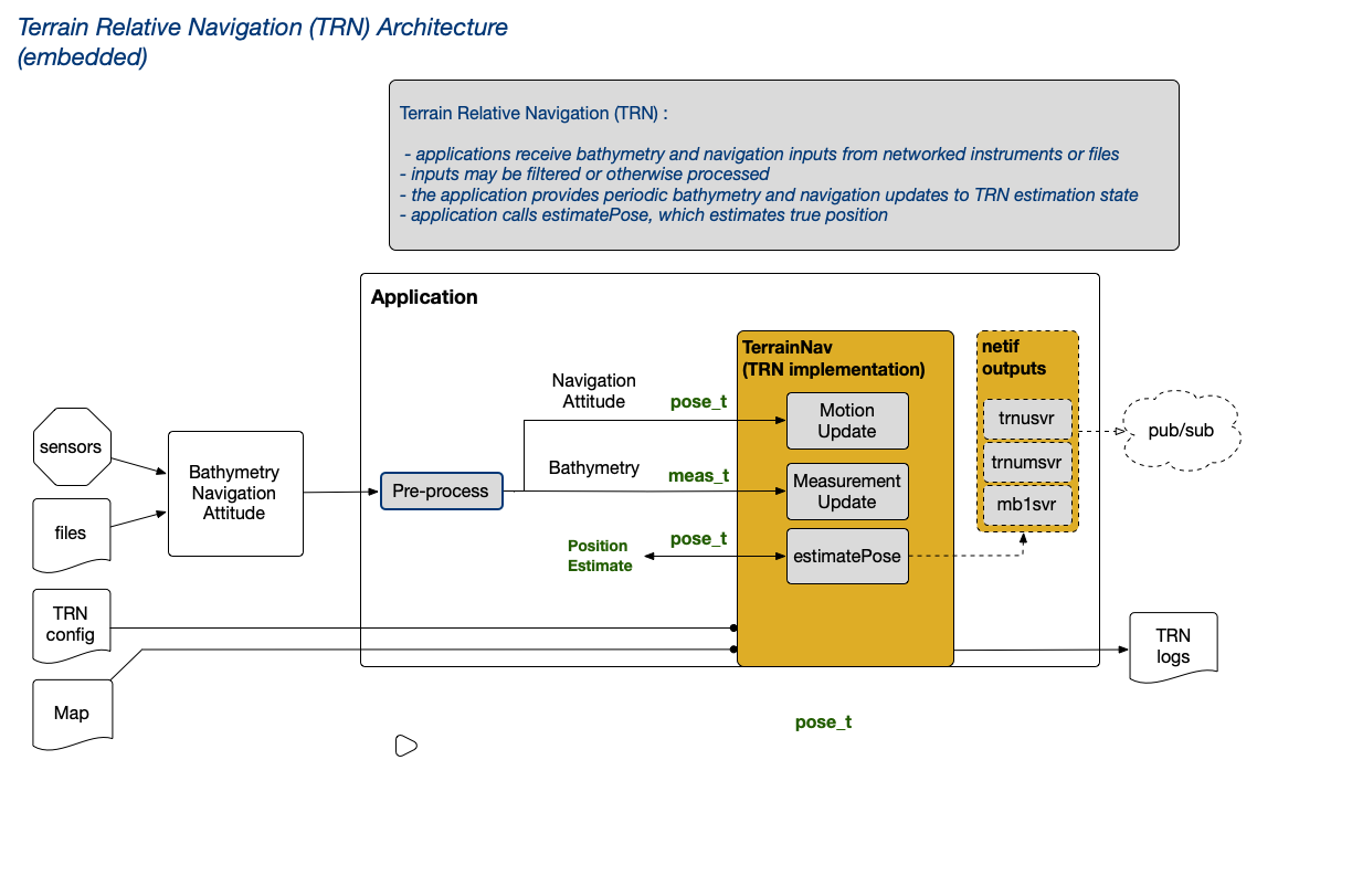
Fig: TRN Architecture (embedded)
A TRN instance may be embedded in an application (as shown above), or run as a separate process and operated over a network using a TCP client.
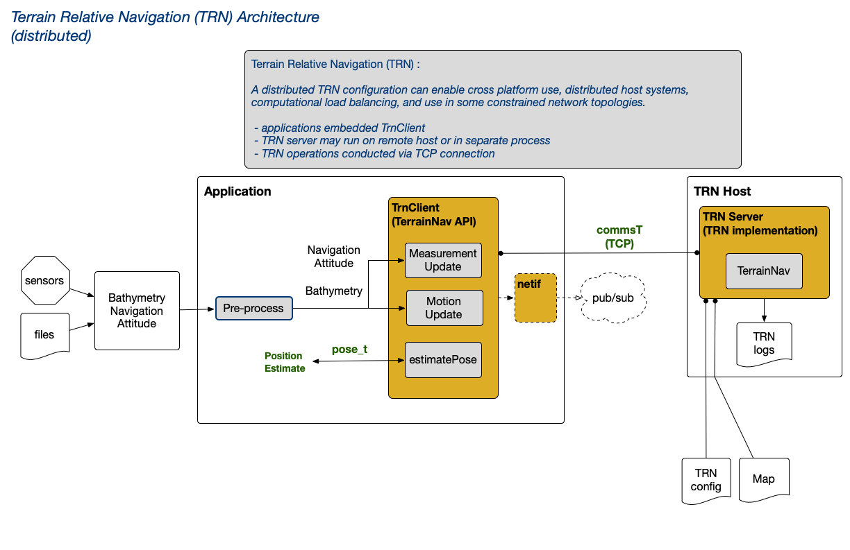
Fig: TRN Architecture (distributed)
libtrnav may be thought of in terms of several conceptual layers, some of which are provided by libtrnav, and application-specific layers implemented by users. Some examples of application-specific code may be found in libtrnav/opt.
The following diagram illustrates TRN architectural elements and some existing implementations.
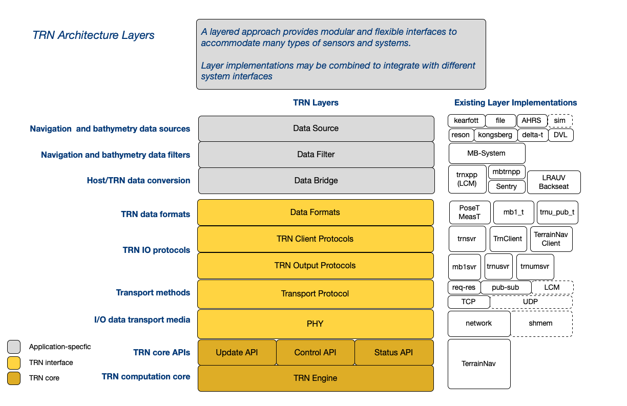
Fig: TRN Architectural Layers
The TRN core implementation provides C++ and C APIs. Key data structures and APIs are briefly summarized below; the TRN Doxygen documentation is recommended for browsing the source and understanding component relationships and details.
libtrnav APIs
Table: libtrnav API summary
| API | Description | Directory | Sources |
|---|---|---|---|
| TRN C++ | TRN core classes | terrain-nav qnx-utils newmat |
|
| TRN C| | TRN core C wrappers | trnw | trnw |
| netif | TRN network interfaces | trnw | netif trnif_msg trnif_proto mb1_msg |
| TRN clients | TRN client interfaces | utils | TerrainNavClient TrnClient |
libtrnav Component Classes
libtrnav Interfaces
Table: libtrnav interface summary
| Interface | Description | Sources |
|---|---|---|
| TerrainNav | TRN object API | Octree OctreeNode OctreeSupport OctreeTestCode PositionLog TNavBankFilter TNavConfig TNavExtendKalmanFilter TNavFilter TNavPFLog TNavParticleFilter TNavPointMassFilter TNavSigmaPointFilter TRNUtils TerrainMap TerrainMapDEM TerrainMapOctree TerrainNav TerrainNavLog TrnLog genFilterDefs mapio matrixArrayCalcs myOutput particleFilterDefs structDefs trn_common trn_log qnx-utils |
| TRN server | TRN TCP socket | trn_server trn_log TNavConfig TerrainNav |
| netif | netif trnif_msg trnif_proto mb1_msg |
R1C3 |
| MB1 server | MB1 UDP socket (output) | netif |
| TRNU server | TRN TCP socket (output) | netif |
| TRNUM server | TRN UDP multicast socket (output) | netif |
| TrnClient | TRN client Extends TerrainNavClient to enable deferred initialization preferred for new applications |
TrnClient |
| TerrainNavClient | TRN Client | TerrainNavClient |
libtrnav Data Structures
Table: libtrnav data structure summary
| Data Structure | Source/th> | Description/th> |
|---|---|---|
| PoseT | terrain-nav/structDefs.h | Position Update Input, Position Estimate Output |
| MeasT | terrain-nav/structDefs.h | Motion (process) Update Input |
| SensorT | terrain-nav/structDefs.h | Bathymetry sensor configuration (geometry, process noise, measurement noise) |
| CommsT | terrain-nav/structDefs.h | TRN server IO messages |
| trnu_pub_t | trnw/trn_msg.h | TRN UDP output message |
| mb1_t | trnw/mb1_msg.h | MB1 format bathymetry output message |
| trncli_t | trnw/trn_cli.h | TRN client (C API) |
| trnmsg_header_t trnmsg_t trn_type_t trn_float_t trn_init_t trn_meas_t trn_triplet_t trn_box_t trn_pose_t |
trnw/trnif_msg.h | TRN network interface message structures (C API) |
| trnucli_t | trnw/trnu_cli.h | TRN UDP client |
| trn_config_t | trnw/trnw.h | TRN configuration (C API) |
Integration
Integration Overview
There are a number of application-specific considerations to be resolved when integrating TRN into a host system:
System Requirements
Processing resources needed for TRN
Input Processing
Sensors, sampling strategies, and protocols for bathymetry, navigation, and attitude sensors. Converting sensor data to TRN input formats.
TRN implementation
TRN implementation selection: embedded, distributed (network), online (real-time), or offline (post-processing).
Outputs
Interpretation and distribution of TRN outputs
Configuration
Handling TRN configuration parameters
These are detailed in the sections that follow.
System Requirements
TRN will perform reasonably well on pentium class hardware with 8 GB of RAM, depending on the working processing load. On the other hand, SBCs like Raspberry PI and Beaglebone with small ARM processors may not be adequate. As a general guideline, it's helpful to run TRN on a well-provisioned host.
libtrnav builds and runs on MacOS, Linux, and Windows (using Cygwin).
As mentioned elsewhere, a particle filter size of N=10000 seems to be a good default (and is currently used in all applications).
The following table summarizes the computing environment for several existing TRN applications.
| Application | CPU | RAM | OS | Notes |
|---|---|---|---|---|
| Dorado | x86 i5? 32/64-bit PC-104 ? MHz | 8 GB | Windows XP/Cygwin | Reson sonar computer |
| Sentry | x86 i7 64-bit PC-104 ? MHz | 8 GB | Ubuntu 22.04 Linux | WHOI Datapod backseat computer |
| LRAUV | ARM 64-bit | 16 GB ? MHz | Custom Linux kernel | nvidia jetson nano backseat computer |
| ROV | x86 64-bit Apple Macbook Pro | 16 GB | MacOS | |
| Offline testing/sim | x86 64-bit | 4 GB RAM | Ubuntu 18+ | VMWare guest on MacOS host |
TRN implementation
libtrnav include a pair of TRN particle filter implementations that may be used to develop applications: embedded and distributed. Selection depends on the application's architecture, host computing platform, and network topology. Some applications combine different implementations for different contexts (e.g. on-line real-time vs off-line post-processing applications).
Embedded
A TRN (TerrainNav) object may be embedded in an application, then configured and managed directly by application code. The TerrainNav class is written in C++, though C bindings are available using the trnw (TRN wrapper) API.
The C++ API has a number of constructors with different configuration information, for example:
// map path
// vehicle spec path (file containing sensor types, geometry)
// filter type: TRN filter implementation ID (typically particle filter)
// map type: Map type ID (typically binary octree)
// directory: TRN log directory

TerrainNav(char *mapName, char *vehicleSpecs,
             const int &filterType, const int &mapType, char *directory);

// This version includes an optional particles file path, which is used to store particle state information

TerrainNav(char* mapName, char* vehicleSpecs, char* particles,
             const int& filterType, const int& mapType, char* directory);
The C API constructor takes a trn_cfg_t structure. The structure members are used to invoke a C++ constructor.
wtnav_t *wtnav_new(trn_cfg_t *cfg);
Applications using an embedded TRN instance include MB-System (mbtrnpp application) and Long Range AUV.
Distributed (TRN server)
TRN also includes an implementation called TRN server (trn-server). TRN server is an application that may be built for Linux, MacOS and Windows (using Cygwin). It includes a TRN instance with a TCP socket interface, enabling clients to perform TRN operations (motion/measurement updates, position estimates) remotely. Each TRN server supports a single client connection.
In this way, distributed applications may be partitioned in a more modular way, with TRN functions hosted in a location, for example, with more compute resources or more convenient network or physical location. It is useful in system architectures with isolated core vehicle functions.
In a distributed implementation, application code uses one of several TRN clients. The client API is similar to the TerrainNav API, with added socket configuration. Clients include TrnClient and TerrainNavClient.
Applications the use a distributed implementation include Dorado AUV and it's simulator.
A variant of distributed implementation uses an embedded TRN instance in conjunction with pub-sub (UDP, UDP multicast) interfaces to distribute TRN output. In this scenario, multiple clients receive TRN outputs, while TRN is managed by the application. The UDP network interface supports TRN filter resets. UDP multicast is unidirectional, and does not support any TRN configuration/control.
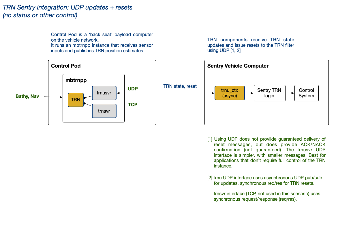
Fig: Sentry TRN Architecture (distributed)
Applications using a distributed implementation include WHOI ROV Sentry, and MBARI ROV Ventana. In both cases, MB-System (mbtrnpp) manages the TRN operations, and publishes outputs used by clients to inform navigation and control.
Using TRN Offline
TRN is expected to work in an online (real-time) context, in which TRN outputs inform navigation. For testing and simulation, TRN may also be used in an offline context, where TRN receives input from files or test software rather than sensors. Offline applications (e.g. simulation) may run in discreet time, i.e. faster than real time.
TRN does not have or impose any intrinsic timing dependencies or requirements. The primary consideration in relationship to timing is TRN computational load/delay, which depends on the size of the particle filter and host computing resources (memory, CPU, disk speed).
Input Processing
As it is very application-specific, input processing accounts for the majority of effort required for TRN integration.
Applications may receive TRN input data from sensors (via serial, sockets), files, databases, messaging middleware framework, e.g. LCM, ROS, ZeroMQ, or a combination of these. Each of these have their own formats, timing, and other considerations that depend on the specific input source.
Whatever the source, bathymetry, navigation and attitude inputs must be acquired, potentially processed (e.g. parsing and unit conversion), and formatted into structures appropriate for TRN.
Because it is so specific to context, libtrnav doesn't include a general purpose framework for managing sensor input streams; these are outside the scope of libtrnav, available elsewhere, and the choice is more sensibly to be left to the developer.
However, libtrnav's application-specific code (libtrnav/opt) includes a number of examples with different platforms and architectures.
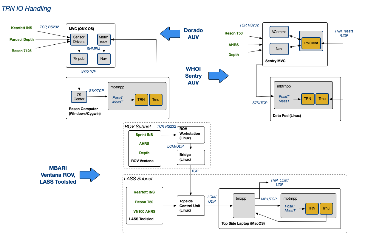
Fig: TRN IO Examples
In general, TRN input rates are typically lower than sensor sampling rates. In fact, as described in the users guide, over-sampling can correlate inputs, leading to to mis-convergence. Sampling for TRN should ensure adequate independence between measurements; the TRN update rate may depend on vehicle speed, sensor orientation and terrain.
For reference, the following table lists output rates for some sensors used for TRN.
| Application | bathymetry | navigation |
|---|---|---|
| Dorado | Kongsberg EM2040 200/400 Khz @ 3 Hz Reson 7125 @ 3 Hz Reson T50 @ ? Hz |
Kearfott INS ? Hz |
| Sentry | Kongsberg EM2040 200/400 Khz @ ? Hz | INS @ ? H |
| LRAUV | RDI Pathfinder DVL @ 0.5 Hz | AHRS-M2 @ 1.5 H |
| ROV | DVL @ ? Hz Kongsberg EM2040 @ 3 Hz (LASS) |
Sprint INS @ 15? Hz |
Input streams may be decimated (sub-sampled) as needed. Sensor data streams are typically at different rates. Bathymetry inputs should correspond to the location and attitude associated with them. If data are buffered, be aware that updates should not use data that is too old, or for which there is significant temporal skew between motion and measurement updates.
As a guideline, TRN inputs should be spaced by at least ~3 m. For example, if a platform is moving at 1 m/s and using a sonar pinging at 3 Hz, there are 3 samples/m; every 9th sample would be ~ 3m apart.
Input data are ultimately converted to the TRN data structures PoseT and MeasT for process and measurement updates, respectively. The C API uses wmeast_t and wposet_t, which are simple C wrappers around PoseT and MeasT objects:
PoseT, MeasT (terrain-nav/structDefs.h)
void TerrainNav::motionUpdate(poseT* incomingNav)
void TerrainNav::measUpdate(measT* incomingMeas, const int& type)
wposet_t, wmeast_t (trnw/trnw.h, .cpp)
void wtnav_motion_update(wtnav_t *self, wposet_t *incomingNav)
void wtnav_meas_update(wtnav_t *self, wmeast_t *incomingMeas, const int type)
poseT
struct poseT {

    double x, y, z;                // North, East, Down position (m)
    double vx, vy, vz, ve;         // Vehicle velocity wrto terrain (m/s) [1]
    double vw_x, vw_y, vw_z;       // Vehicle velocity wrto water (m/s) [1]
    double vn_x, vn_y, vn_z;       // Vehicle velocity wrto an inertial frame (m/s) [1]
    double wx, wy, wz;             // Vehicle angular velocity wrto an inertial frame (rad/s) [1]
    double ax, ay, az;             // Vehicle aceleration wrto an inertial frame (m/s^2) [1]
    double phi, theta, psi;        // 3-2-1 Euler angles relating Body frame to
                                   // an inertial NED frame (rad).
    double psi_berg, psi_dot_berg; // TRN states

    double time;                   // Time (seconds since 01-01-1970T00:00:00)

    bool dvlValid;                 // DVL measurement valid flag
    bool gpsValid;                 // GPS measurement valid flag
    bool bottomLock;               // DVL bottom lock valid flag

    double covariance[N_COVAR];    // Covariances: XYZ, phi, theta, psi, wy, wz
                                   // (passively stable in roll) (see above units)

    // [1] coordinates in Body Frame

    poseT();
    poseT& operator=(const poseT& rhs);
    poseT& operator-=(const poseT& rhs);
    poseT& operator+=(const poseT& rhs);

    int   serialize(char *buf, int buflen);
    int unserialize(char *buf, int buflen);
};
The PoseT structure is used for both input and output to TRN.
For input, most applications use a subset of these fields:
 time
 x, y, z
 vx, vy, vz
 phi, theta, psi
 dvlValid
 gpsValid
 bottomLock
vx is strictly required for TRN; vy, vz are optional.
To fully initialize, TRN requires that a motion update be received with vx (along-track velocity) not equal to zero, which indicates forward motion. Until that happens, TRN emits an error message indicating that TRN has not been initialized when measurement updates are received. Once motion has been established, motion and measurement updates may occur in any order.
vx is used for most configurations to indicate motion, and its value is not critical, but must be != 0 in order for TRN to initialize.
In general, TRN does not require velocity to operate, but in some contexts, velocity may be integrated to determine position, in which case it is needed.
For output, a PoseT instance is passed into estimatePose, which populates these fields:
 time            // time
 x,y,z           // position estimate
 covariance      // covariances (uncertainties)
                 // covariance[0] : x/N covariance
                 // covariance[2] : y/E covariance
                 // covariance[5] : z/D covariance
                 // covariance[1] : XY covariance (?)
The remaining fields are somewhat application-specific, and may be used in some TRN configurations.
measT
The measT structure is used for measurement update (bathymetry) input. In libtrnav, measurements are often referred to as beams; this stems from the fact that TRN bathymetry sensors are historically acoustic instruments, i.e. sonars and DVLs. They could, however, include LIDAR or other sensors. Here, measurement and beams are used interchangeably.
struct measT {
    double time;              // Measurement time (s)
    int dataType;             // Sensor type [1]
    double phi, theta, psi;   // 3-2-1 Euler angles relating Body frame to
                              // an inertial NED frame (rad).
    double x, y, z;           // North, East, Down position (m)

    double* covariance;       // covariance array [2]
    double* ranges;           // beam ranges [2]
    double* crossTrack;       // beam component perpendiclar to velocity [2]
    double* alongTrack;       // beam component parallel to velocity [2]
    double* altitudes;        // beam component downward [2]
    double* alphas;           // alpha values [2]
    bool* measStatus;         // beam measurement valid flag [2]
    unsigned int ping_number; // measurement number
    int numMeas;              // number of beams
    int* beamNums;            // beam numbers (for sensors w/ variable beams) [2]

    // [1] sensor type enumerations
    //      1: DVL
    //      2: Multibeam
    //      3: Single Beam
    //      4: Homer Relative Measurement
    //      5: Imagenex multibeam
    //      6: Side-looking DVL
    // [2] array with dimension numMeas

    measT();
    measT(unsigned int nummeas, int datatype);
    ~measT();
    void clean();
    measT& operator=(const measT& rhs);

    int   serialize(char *buf, int buflen);
    int unserialize(char *buf, int buflen);
};
measT is passed into measUpdate, with these fields populated:
 time
 dataType
 x, y, z
 phi, theta, psi
 ranges
 crossTrack
 alongTrack
 altitudes
 measStatus
 ping_number
 numMeas
 beamNums
Sensor Geometry and Measurements
A bathymetry source with a single beam is sufficient for TRN to produce reliable estimates. While such sensors exist, acoustic sensors with multiple beams are commonly used. In the context of TRN input, each beam is an independent measurement. Each sounding of a sensor with N beams (e.g. DVLs, multibeam sonars) produces N measurements with a common timestamp. Thus the measT structure contains a single timestamp with arrays of beam components. Conversely, a measT structure may contain a single beam. If there were a significant time difference between beams, it would be necessary to timestamp them separately in separte measurement updates. Again, a measurement's time, location and attitude must correspond with it's bathymetry.
The measT dataType member (sensor type) is used to enable TRN to differentiate between different beam geometries.
TRN uses sensor type to select appropriate validation algorithms for certain types.
In the TRN filter base class, TNavFilter, sensor type is used to project measT ranges onto sensor frame components: alongTrack, acrossTrack, altitude. dataType also effects how variances are computed.
For multibeam sensors, TRN uses the measT beam component members (alongTrack, acrossTrack, altitudes). Multibeam sensors are assumed to have coplanar beams, extending radially from the sensors, i.e. a fan.
For DVL and other types, TRN uses the measT ranges member. DVL is assumed to have a radial array of 4 downward looking beams, with azimuth and elevation angles defining the orientaton.
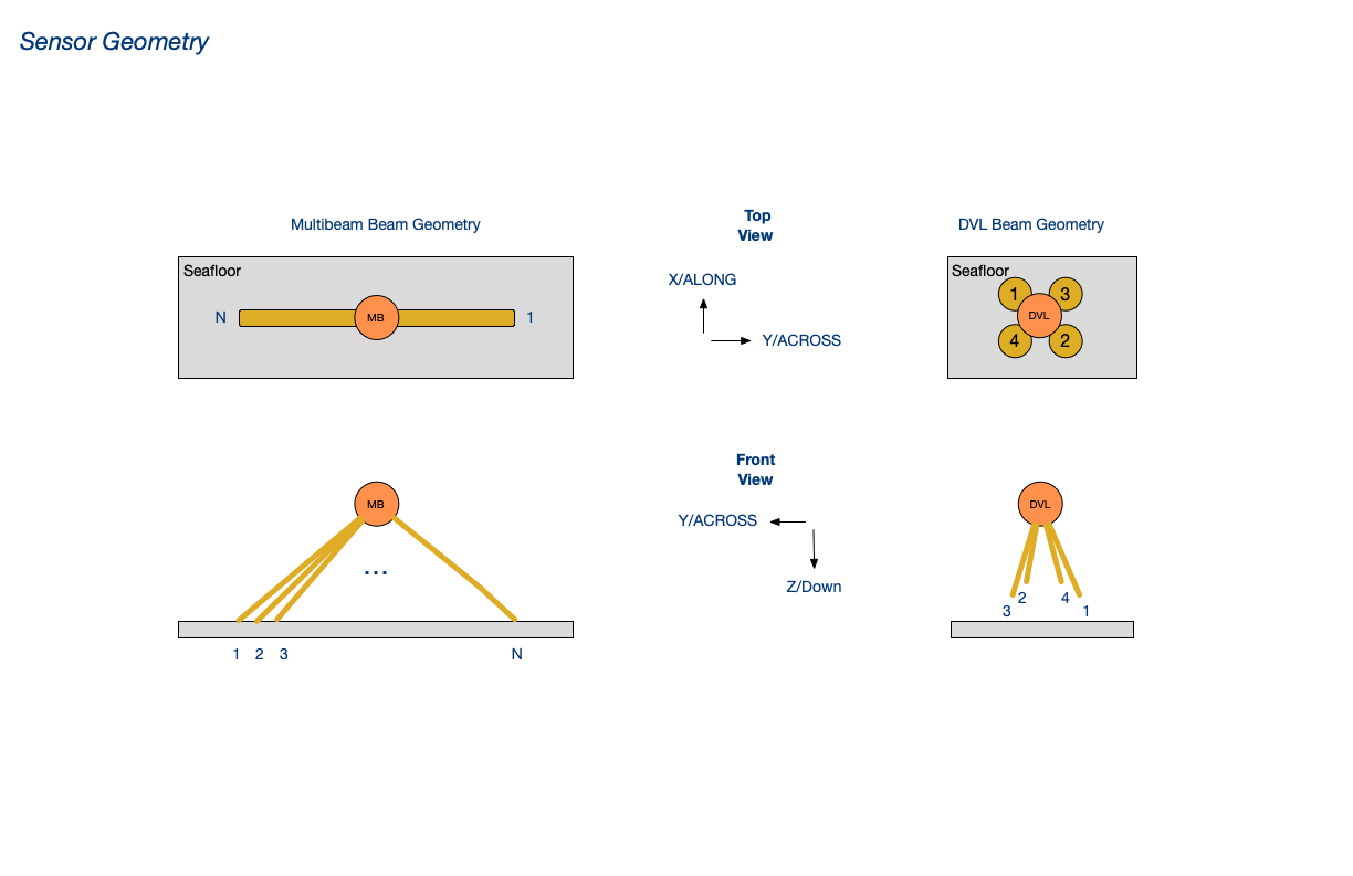
Fig: Sensor Beam Geometry
TRN configuraton parameters describing sensor types and geometry are specified in vehicle specifications and sensor configuration files, further described in the configuration section.
Coordinate Systems
Both poseT and measT use a cartesian coordinate systems, with dimensions in meters. Maps are generally Mercator Projections. Both UTM and local projections have been used. When using UTM, there is significant error when operating in a region far from the origin. Such errors are proportional to the distance from the origin. Using a local Mercator projection enables the origin to be defined in the region of interest, reducing the errors.
Latitude and longitude is the scheme most commonly used by position and navigation sensors. TRN position inputs must use the map's cartesian coordinates (northings and eastings). libtrnav includes the GCTP library for converting lat/lon to UTM; it does not support other projections. Libraries such as libproj may be used, which can support conversions between lat/lon and a wide range of existing and custom projections.
libtrnav provides a class called GeoCon that serves as a wrapper for geocoordinate conversions. It provides a common API that enables conversions with different underlying implementations to be passed into functions using a single type.
GeoCon currently supports GCTP and libproj implementations, but could be extended to support other implementations. GeoCon also has a C API; the C type is wgeocon_t.
The TRN C API (trnw.cpp) functions (for converting MB1 bathymetry records to poseT and measT) demonstrate how GeoCon is used.
int wposet_mb1_to_pose(wposet_t **dest, mb1_t *src, wgeocon_t *geocon)
int wmeast_mb1_to_meas(wmeast_t **dest, mb1_t *src, wgeocon_t *geocon)
Outputs
A TRN instance (or client) obtains the current TRN estimate using the estimatePose method.
# CPP API (TerrainNav.h)
virtual void estimatePose(poseT* estimate, const int &type);

# C API (trnw.h)
void wtnav_estimate_pose(wtnav_t *self, wposet_t *estimate, const int type);
The poseT argument is used to return the TRN update, i.e., the position estimate and covariances, along with measurement time, location, and attitude.
The type argument is an enumerated type to select whether the filter value returned is the MLE (maximum likelihood estimator) or MMSE (minimum mean squared error). As described above, the MLE corresponds tallest peak in the likelihood distribution, and MMSE is the lowest error value. Typically MMSE is used, as MLE may be skewed by multimodal distributions. The two could potentially used in conjunction (with some computational cost) to signal convergence, since they should coincide when TRN is truly converged.
Convergence
The value returned by TerrainNav::lastMeasSuccessful() indicates whether the most recent measurement update resulted in a TRN estimate update; it does not indicate whether TRN is converged or valid.
# CPP API (TerrainNav.h)
virtual inline bool lastMeasSuccessful();
# C API (trnw.h)
wtnav_last_meas_successful(wtnav_t *self);
There is a virtual method that nominally returns a boolean convergence flag:
# CPP API (TerrainNav.h)
bool isConverged();
# C API (trnw.h)
bool wtnav_is_converged_(wtnav_t *self);
However, it may be implemented differently by different TRN particle filter implementations, and is not considered to be a reliable indicator of TRN estimate validity. It is recommended that applications implement convergence criteria that make sense in the use context.
For example, the Dorado mapping AUV evaluates NED covariances over a series of returns. A number of consecutive successful updates with covariances that fall within a specified threshold consitute convergence. Once converged, TRN estimates are considered valid until an measurement falls outside the convergence threshold.
Applications may also implement logic to reset the TRN filter under some circumstances. There are different reset mechanisms that allow a 'global' reset (start fresh using the full spatial particle distribution), or a 'local' reset that redistributes particles using the last valid offset or a specified bounding box. A local reset may be useful when covariances are suspiciously small, possibly indicating that TRN has converged on incorrectly on a local minimum. In terrain with adequate information, TRN should reconverge quickly to a similar value when a local reset is made.
In brief: convergence criteria and requirements are somewhat application-specific, and the application should determine whether to use TRN estimates.
Log Files
TRN generates log files that include a message logs for debugging, and data logs containing input and output.
| Log File | Format/th> | Contents/th> |
|---|---|---|
| trn.log.nnnn | text | TRN message log (segmented, 0000-9999) |
| TrnIO.log | binary | TRN data log (multiple record types) |
| TerrainNav.log | binary | TRN data log (single record type, legacy) |
| TNavPFLog.log | binary | TRN particle state log (a lot of data) |
The TrnIO log may contain multiple record types, identified with IDs:
MOTN_IN = motion update input
MEAS_IN = measurement update input
MSE_OUT = MMSE output
MLE_OUT = MLE output
TrnIO record types are dynamically sized, and contain minimal record headers and sync patterns, making them efficient in terms of storage and straightforward to search and parse, even if corrupted.
The TerrainNav log uses a single record type to record (MLE, MMSE) outputs and inputs, which is less efficient; it writes all fields, including arrays (which are statically sized to TRN_MAX_BEAMS), whether they are used or not. Also, record type is ambiguous, and do not contain any sync patterns.
Logs are written to the directory passed to TerrainNav constructor, along with configuraton files used to configure the TRN instance.
Network Output
For TRN applications that require TRN updates to be distributed, e.g. to multiple processes or across networks, libtrnav provides components implementing socket-based TRN IO, collectively referred to as the netif API.
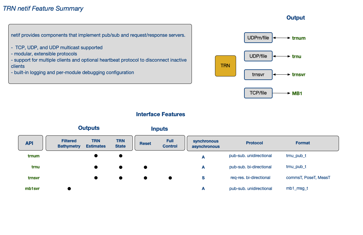
Fig: netif Feature Summary
The following code example shows how a TRN UDP update server is started:
wtnav_t *trn_instance...;

// define a server resource bundle
trnuif_res_t rr_resources={0},*g_trnu_res=&rr_resources;

// log directory, session ID strings
const char *log_dir=."";
const char *session_str="202501010000";
// socket address
const char *host = "192.168.1.1";
int port = 270001;
// disable server heartbeat (< 0)
int hbto = -1;

// create a netif TRN UDP server (trnusvr)
netif_t *svr = netif_new("trnusvr",             // server ID
                         host,                  // socket address
                         port,
                         ST_UDP,                // socket type
                         IFM_REQRES,            // protocol (req/res or pub/sub)
                         hbto,                  // heartbeat config
                         trnif_msg_read_trnu,   // protocol methods
                         trnif_msg_handle_trnu, // defined in netif_proto.c
                         trnif_msg_pub_trnu);

if(NULL!=svr){

    // configure network resource bundle, which contains
    // references needed for server to invoke callbacks

    // TRN instance
    g_trnu_res->trn = trn_instance;

    // TRN reset callback function
    g_trnu_res->reset_callback = s_mbtrnpp_trnu_reset_callback;

    // TRN reset using offset callback function
    g_trnu_res->reset_ofs_callback = s_mbtrnpp_trnu_reset_ofs_callback;

    // TRN reset using box callback function
    g_trnu_res->reset_box_callback = s_mbtrnpp_trnu_reset_box_callback;

    netif_set_reqres_res(svr,g_trnu_res);
    netif_show(svr,true,5);

    // initialize server message log
    netif_init_log(svr, "trnusvr", log_dir, session_str);
    mlog_tprintf(svr->mlog_id,"*** trnusvr session start [%s] ***\n", session_str);
    mlog_tprintf(svr->mlog_id,"libnetif v[%s] build[%s]\n",netif_get_version(),netif_get_build());

    // start server
    retval = netif_connect(svr);
} else {
    fprintf(stderr,"%s:%d - ERR allocation\n",__FUNCTION__,__LINE__);
}

// do stuff...

// release trnusvr resources
 netif_destroy(&trnusvr);
Binary Logs using mframe library
Some libtrnav utilities use mframe, a C library maintained in the MBARI git repo
https://bitbucket.org/mbari/mframe
mframe encapsulates commonly used components including
- files
- sockets
- serial ports
- threads
- clocks
- config files
- debug output writers
- logs
- containers
- utilities
for reuse and reliability, using a simple and consistent API.
The mframe log class, mlog, may be used to create binary or ascii logs.
The example below demonstrates uses mlog to create a TRN update log.
// log handle
mlog_id_t trnu_blog_id = MLOG_ID_INVALID;

// log default configuration
mlog_config_t trnu_blog_conf = {100 * SZ_1M, ML_NOLIMIT, ML_NOLIMIT, ML_OSEG | ML_LIMLEN, ML_FILE, ML_TFMT_ISO1806};

// log path
char *trnu_blog_path = NULL;

// set the log path
trnu_blog_path = (char *)malloc(512);
sprintf(trnu_blog_path, "%s//%s-%s%s", mbtrn_cfg->trn_log_dir, TRNU_BLOG_NAME,
        s_mbtrnpp_session_str(NULL,0,RF_NONE), MBTRNPP_LOG_EXT);

// create log
trnu_blog_id = mlog_get_instance(trnu_blog_path, &trnu_blog_conf, TRNU_BLOG_NAME);

// print log configuration summary to console
mlog_show(trnu_blog_id, true, 5);

// open the log
mlog_open(trnu_blog_id, flags, mode);


// do stuff...

// TRN update structure (filled in elsewhere)
trn_update_t *pstate...

// log it
trn_pub_blog(pstate, trnu_blog_id);

// when done...

// release log resources
mlog_delete_instance(trnu_blog_id);


// write TRN update to log
trn_pub_blog(trn_update_t *update,
                             mlog_id_t log_id)
{
    int retval=-1;

    if(NULL!=update && log_id!=MLOG_ID_INVALID){

        retval = 0;
        int iobytes = 0;
        double offset_n = update->mse_dat->x - update->pt_dat->x;
        double offset_e = update->mse_dat->y - update->pt_dat->y;
        double offset_z = update->mse_dat->z - update->pt_dat->z;

        // serialize data
        trnu_pub_t pub_data = {
            TRNU_PUB_SYNC,
            {
                {update->pt_dat->time,update->pt_dat->x,update->pt_dat->y,update->pt_dat->z,
                    {update->pt_dat->covariance[0],update->pt_dat->covariance[2],update->pt_dat->covariance[5],update->pt_dat->covariance[1]}
                },
                {update->mle_dat->time,update->mle_dat->x,update->mle_dat->y,update->mle_dat->z,
                    {update->mle_dat->covariance[0],update->mle_dat->covariance[2],update->mle_dat->covariance[5],update->mle_dat->covariance[1]}
                },
                {update->mse_dat->time,update->mse_dat->x,update->mse_dat->y,update->mse_dat->z,
                    {update->mse_dat->covariance[0],update->mse_dat->covariance[2],update->mse_dat->covariance[5],update->mse_dat->covariance[1]}
                },
                {update->mse_dat->time,offset_n,offset_e,offset_z,
                    {update->mse_dat->covariance[0],update->mse_dat->covariance[2],update->mse_dat->covariance[5],update->mse_dat->covariance[1]}
                },
                {use_offset_time,use_offset_n,use_offset_e,use_offset_z,
                    {use_covariance[0],use_covariance[1],use_covariance[2],use_covariance[3]}
                },
            },
            update->reinit_count,
            update->reinit_tlast,
            update->filter_state,
            update->success,
            update->is_converged,
            update->is_valid,
            update->mb1_cycle,
            update->ping_number,
            n_converged_streak,
            n_converged_tot,
            n_unconverged_streak,
            n_unconverged_tot,
            update->mb1_time,
            reinit_time,
            update->update_time
        };

        // write data to log
        if( (iobytes=mlog_write(log_id,(byte *)&pub_data, sizeof(pub_data)))>0){
            retval=iobytes;
        }
    }
    return retval;
}
Configuration
TRN applications need to manage configuration parameters. that may need to be incorporated into the host system configuration mechanism as part of an integration process.
TRN configuration parameters are detailed below; these include configuration files, compile time options, and run-time
Configuration Files
- files: map, vehicle spec, device spec : optional: particles
TRN constructors require a map file or directory, and a vehicle config file. The vehicle config file references one or more sensor config files. An optional particles file may also be used.
Maps
A TRN map may be either a binary octree (.bo) or digital elevation map (DEM, .grd format). A map may be provided as a path to a single file or a directory containing a set of map map tiles (sub-maps) and a key file describing the tile boundaries. Since maps can be large, tiled maps limit run-time memory use; switching between tiles incurs modest run-time delays. The tiled map key file (tiles.csv) is a CSV file that includes a header (specifies number of tiles) and a line for each tile that includes filename, origin easting, origin northing:
TileName, Easting, Northing, <number of tiles>
<file>, <origin Easting>, <origin northing>
...
Example: tiles.csv
TileName , Easting , Northing , 9
PortugueseLedgeTile1.bo , 594250 , 4061250
PortugueseLedgeTile2.bo , 594750 , 4061250
PortugueseLedgeTile3.bo , 595250 , 4061250
PortugueseLedgeTile4.bo , 594250 , 4061750
PortugueseLedgeTile5.bo , 594750 , 4061750
PortugueseLedgeTile6.bo , 595250 , 4061750
PortugueseLedgeTile7.bo , 594250 , 4062250
PortugueseLedgeTile8.bo , 594750 , 4062250
PortugueseLedgeTile9.bo , 595250 , 4062250
libtrnav has a few utilities for working with map files:
| Utility | Description/th> | Use Notes/th> |
|---|---|---|
| csv-octree-maker | generates binary octree map from UTM .csv (DEM) map | csv-octree-maker <file> (w/o .grd extension) additional use notes in source header |
| grd-octree-maker | generates binary octree map from UTM .grd (DEM) ma | grd-octree-maker <file> (w/o .grd extension) additional use notes in source header |
| test-tile | checks tiled map directory | test-tile <directory> |
| transoct | translate .bo origin | transoct file (w/o .grd extension) Writes output to <file>Serm.bo Note: contains hard-coded constants |
| octree2patches | ||
| otree | traverse binary tree and show summary optionally print tree as text |
otree [options] <file> Options: -f -p : print tree to console (a LOT of text) -c : compare to Octree.Print tree stats -v : enable verbose output -h : print this help message |
| bodump | like otree, but less capable, and unfortunately named | bodump <file> |
Vehicle Spec File
The vehicle specification file is a text file with a list of sensor config files, mounting geometry, and a process noise parameter. It's format is rigid; it uses a naming convention \<NAME>_spec.cfg, and its contents are arranged as follows:
# comments...

NAME:<config file name (w/o _spec.cfg)>
NUMSENSORS:<number of sensor entries (integer)>
DRIFTRATE:<process noise figure (floating point)>

SENSORNAME:<sensor spec file name (w/o _spec.cfg)>
DR:<phi>,<theta>,<psi>
DT:<x>,<y>,<z>
...
Example: Vehicle Spec File
# Vehicle specification sheet
#----------------------------
NAME:mappingAUV
NUMSENSORS:3
DRIFTRATE:1.5

SENSORNAME:rdiDVL
DR:0,0,0
DT:0,0,0

SENSORNAME:resonSeabat8101
DR:0,0,0
DT:0,0,0

SENSORNAME:imagenexdeltat
DR:0,0,0
DT:0,0,0
The parameters are described as follows:
| Name | Description/th> |
|---|---|
| NAME | Configuration name (matches file name, w/o _spec.cfg suffix) |
| NUMSENSORS | Number of sensor entries to follow |
| DRIFTRATE | Somewhat of a misnomer, represents TRN process noise, typically 1.5/2 depends on terrain, instruments, etc. |
| SENSORNAME | name of sensor spec file (w/o _spec.cfg suffix) |
| DR | sensor orientation, NED Euler angles in vehicle frame |
| DT | sensor mounting location, distance from vehicle center, m |
Sensor Specification File
The sensor specification files, referenced by the vehicle spec file, are text files with a sensor configuration information. It's format is rigid; it uses a naming convention \<NAME>_spec.cfg, and their contents are arranged as follows:
# comments...
NAME:<sensor name (matches file, w/o _spec.cfg suffix)>
TYPE: <sensor type (integer)>
NUMBEAMS: <number of beams>
PERCENTRANGEERROR: <range error, %>
BEAMWIDTH: <beam width (deprecated)>

# optional fields, type-dependent
PITCH ANGLES:<comma separated list of pitch angles>
DELTA_PITCH:<pitch angle increment>
INIT_YAW ANGLE:<comma separated list of yaw angles>
DELTA_YAW: <yaw angle increment>
INIT_PITCH ANGLES|starting pitch angle(s) in sensor frame, decimal degrees|
| Name | Description |
|---|---|
| NAME | Configuration name (matches file name, w/o _spec.cfg suffix) |
| TYPE | Sensor type enumeration value 1: DVL 2: Multibeam 3: Single Beam 4: Homer Relative Measurement 5: Imagenex multibeam 6: Side-looking DVL |
| NUMBEAMS | number of beams |
| PERCENTRANGEERROR | estimated range error (% of range) |
| BEAMWIDTH | width of beams, m (deprecated) |
| PITCH ANGLES | pitch angles in sensor frame, decimal degrees used for non-multibeam types |
| DELTA_PITCH | pitch angle increment, decimal degrees used for non-multibeam types |
| YAW ANGLES | yaw angles in sensor frame, decimal degrees used for non-multibeam type |
| DELTA_YAW | yaw angle increment, decimal degrees used for non-multibeam types |
Multibeam sensors are assumed to extend radially from the sensor origin. Non-multibeam sensors are assumed to be arranged in a radial array around the sensor origin, with azimuth YAW ANGLE (relative to E) separated by DELTA_YAW. The beams are pitched downward at PITCH ANGLE, optionally incrementing by DELTA_PITCH.
Example: multibeam sensor spec file
# Sensor specification sheet
#----------------------------
NAME: resonSeabat8101
TYPE: 2
NUMBEAMS: 20
PERCENTRANGEERROR: 4
BEAMWIDTH: 1.5

PITCH ANGLES: 0
DELTA_PITCH: 0
INIT_YAW ANGLE: 0
DELTA_YAW: 0
Example: DVL sensor spec file
# Sensor specification sheet
#----------------------------
NAME: rdiDVL
TYPE: 1
NUMBEAMS: 4
PERCENTRANGEERROR: 4
BEAMWIDTH: 3.9

PITCH ANGLES:30, 30, 30, 30
YAW ANGLES: -45, 135, 45, -135

#----------------------------------------------------------------
# Sensor beam configuration diagram:
#
# Beam numbering convention, looking down on Dvl from above.
# x and y are the vehicle axes. x points to port, y to starboard.
#
#                  x
#                  ^
#                  |
#                1 | 3
#                  |------> y
#                4   2
#
# Each beam is spaced 45 degrees from the horizontal/vertical.
# The inclination angle is 30 degrees.
Compile Time Configuration
In addition to the build options that are described above, there are a few macros that are not exposed as configuration options, but that it may be good to be aware of:
| macro | file/th> | description/th> |
|---|---|---|
| TRN_MAX_BEAMS | terrain-nav/structDefs.h | Maximum number of beams for a sensor |
| N_COVAR | terrain-nav/structDefs.h | covariance matrix size for TRN estimates (number of TRN states?) |
| TRN_MSG_SIZE | terrain-nav/structDefs.h | Maximum TRN server (commsT) message length (bytes) |
| MAP_NOISE_MULTIPLIER | terrain-nav/genFilterDefs.h | Multiplier on map noise in particle filter |
| MOTION_NOISE_MULTIPLIER | terrain-nav/genFilterDefs.h | Multiplier on motion noise std in particle filter |
| X_STDDEV_INIT | terrain-nav/genFilterDefs.h | X stdev initial value for TRN resets |
| Y_STDDEV_INIT | terrain-nav/genFilterDefs.h | Y stdev initial value for TRN resets |
| Z_STDDEV_INIT | terrain-nav/genFilterDefs.h | Z stdev initial value for TRN resets |
| PHI_STDDEV_INIT | terrain-nav/genFilterDefs.h | phi (roll) stdev initial value for TRN resets |
| THETA_STDDEV_INIT | terrain-nav/genFilterDefs.h | theta (pitch) stdev initial value for TRN resets| |
| PSI_STDDEV_INIT | terrain-nav/genFilterDefs.h | psi (yaw) stdev initial value for TRN resets |
| MAX_PARTICLES | terrain-nav/genFilterDefs.h | number or particles in particle filter |
Run-time Configuration
As described earlier, TRN constructors include arguments specifying several files. Since the path may differ for a remote TRN instance, only the file names are specified. In other words, a TRN client and server are expected to refer to the same file name, but it may be in different places on their respective hosts. The file paths are specified using environment variables; these should always be set for TRN applications:
| Environment Variable | Description |
|---|---|
| TRN_LOGFILES | path to TRN log output |
| TRN_DATAFILES | path to TRN configuration files (vehicle spec, platform spec |
| TRN_MAPFILES | path to TRN map files |
There are a few uncommonly used environment variables:
| Environment Variable | Description |
|---|---|
| TRN_LOGDIR | Used by TrnClient to set directory used for logs and saving config files |
| TRN_GROUP | Application-specific; UDP multicast group used but trnxpp (/opt/rov) |
| TLP_SESSION | Used by csvlog-player, trnlog-player, mb1log-player to set session name used in output |
| LIBGCTP | Used by gctp/test/test_proj; directory containing geolib.a |
For applications that use LCM, these environment variables may also be used:
| Environment Variable | Description |
|---|---|
| LCM_DEFAULT_URL | LCM URL (UDP multicast group/port, TTL parameter) |
| CLASSPATH | Java classpath, needed by lcm-spy (for lcm.jar, application-specific JAR files) |
Developer Integration Tools
libtrnav does not directly provide libraries or frameworks for integration, i.e. configuration, input handling and logging.
Existing applications may provide helpful examples and resources, some of which are highlighted below:
| Application | Of Interest | Location | About |
|---|---|---|---|
| rov | LCM input | opt/rov | See: trnxpp.hpp pcf_utils.hpp |
| rov | configuration | opt/rov | Application configuration file parsing See: trnxpp_cfg.hpp |
| rov | input source abstraction | opt/rov | Scheme to present hetergeneous input sources using common interfaces See: trn_lcm_input.hpp *_provider_IF.hpp *_input.hpp |
| rov | IO handling | opt/rov | TRN clients, servers, file IO, LCM TRN output See: trnxpp.hpp trnxpp_ctx.hpp |
| rov | logging, per-module debugging | opt/rov | See: log_utils.hpp trn_debug.hpp |
| rov | TRN IO utilities | opt/rov | TRN format conversion, formatted output, matrix calcs, beam component decomposition See: trnx_utils |
| sentry | TrnClient example | opt/sentry | Stand-alone TRN UDP client example (w/ test server) See: README-trndev-build.md trnu-svr trnu-cli |
| lrauv | LCM input | opt/lrauv | |
| MB-System:mbtrnpp |
TRN Applications
Existing TRN applications are documented as a user reference, and to serve as practical examples for developing new applications.
Application: MBARI MB-System
libtrnav has been integrated with MB-System, MBARI's open source mapping tools software package. In that context, the MB-System mbtrnpp (MB-System TRN pre-process) ingests multibeam bathymetry from a variety of multibeam sonar devices, and passes the bathymetry and navigation to libtrnav for TRN processing.
This capability is used in Dorado mapping AUV and WHOI Sentry AUV, and is being developed for the Ventana ROV and Low-Altitude Survey Sled mapping tool sled.
Overview
mbtrnpp (MB-System TRN pre-process) is an application that is part of the open source MB-System mapping package (here on github ).
While it is not a part of libtrnav, it plays a role in a number of TRN use cases across platforms. It serves as a TRN instance for multibeam sonar data across in many formats, including MB1, a generic format that could be used for other applications. It also contains example implementations of network interfaces That being so, it is worth describing it in some detail.
Its function is to filter bathymetry and navigation data, the use TRN to estimate location/offset in relation to an existing map. This is done primarily in the context of AUV mapping missions, and is used in several contexts, including MBARI Dorado and ROV/LASS, WHOI Sentry.
mbtrnpp can read multibeam sonar data in a number of different formats, in real time or online. The underlying MB-System code has facilities for parsing the sonar data streams, which typically have navigation/attitude data in them. The underlying MB-System libraries are used to parse and filter the inputs, and generate MB1 records, which include bathymetry and navigation data.
Using the libtrnav C wrapper API (libtrnw), the MB1 records are used to generate PoseT and MeasT data structures and passed to an embedded TRN instance.
mbtrnpp uses the libtrnav network interface libraries (netif) to publish MB1 records and TRN updates (i.e. TRN inputs and outputs) via several pub/sub interfaces:
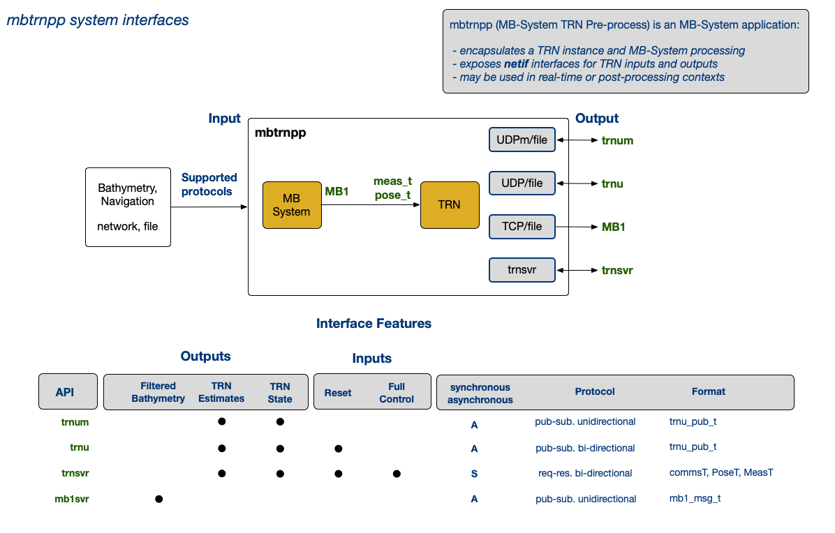
Fig: mbtrnpp system interfaces
mbtrnpp configuration
The configuration file for mbtrnpp contains configuraton items for TRN, as well as the mbtrnpp application.
| Option | Type | Description | ||||||||||||||||
|---|---|---|---|---|---|---|---|---|---|---|---|---|---|---|---|---|---|---|
| verbose=d | int | verbose output | ||||||||||||||||
| help | - | print use info | ||||||||||||||||
| config=path | string | configuration file path | ||||||||||||||||
| log-directory=path | string | log directory path | ||||||||||||||||
| input=datalist|file|socket_definition | string | MB-System datalist file path | ||||||||||||||||
| output=file|'socket' | string | output file path or socket descriptor (?) | ||||||||||||||||
| swathwidth=value | float | total beam swath in degrees | ||||||||||||||||
| soundings=value | int | number of beams to use | ||||||||||||||||
| median-filter=threshold/nx/ny | float/int/int | median filter threshold and dimensions | ||||||||||||||||
| format=format | int | data input format (defined in mbio/mb_format.h) | ||||||||||||||||
| platform-file=file | string | platform file path | ||||||||||||||||
| platform-target-sensor=sensor_id | int | - | ||||||||||||||||
| tide-model=file | string | tide model file path | ||||||||||||||||
| statsec=f | float | log performance metrics every f seconds | ||||||||||||||||
| statflags=<flag>[:<flag>...]; where flags include MSF_STATUS MSF_EVENT MSF_ASTAT MSF_PSTAT MSF_READER |
string | status output selection flags
|
||||||||||||||||
| delay=n | int | loop delay (seconds) | ||||||||||||||||
| trn-en=b | bool | enable TRN processing | ||||||||||||||||
| trn-dev=s | string | - | ||||||||||||||||
| use-proj[=b] | bool | use libproj | ||||||||||||||||
| projection=projection_id | int | projection ID (PROJ) | ||||||||||||||||
| trn-crs=s | string | libproj CRS string used for TRN | ||||||||||||||||
| trn-utm=d | int | TRN UTM zone | ||||||||||||||||
| trn-map=s | string | TRN map file name/directory | ||||||||||||||||
| R1C1 | R1C2 | R1C3 | ||||||||||||||||
| trn-par | string | TRN particles file name | ||||||||||||||||
| trn-mid=s | R1C2 | trn config mission ID (used for log directory prefix, e.g. [mbtrnpp TRN_LOGFILES environment variable must be set] |
||||||||||||||||
| trn-cfg=s | string | TRN config file name | ||||||||||||||||
| R1C1 | R1C2 | R1C3 | ||||||||||||||||
| trn-mtype | string? int? | TRN map type | ||||||||||||||||
| trn-sensor-type | R1C2 | TRN sensor type 1: TRN_SENSOR_DVL 2: TRN_SENSOR_MB 3: TRN_SENSOR_PENCIL 4: TRN_SENSOR_HOMER 5: TRN_SENSOR_DELTAT |
||||||||||||||||
| trn-ftype | int | TRN filter type 0: TRN_FILT_NONE 1: TRN_FILT_POINTMASS 2: TRN_FILT_PARTICLE 3: TRN_FILT_BANK |
||||||||||||||||
| trn-fgrade | int | TRN filter grade | ||||||||||||||||
| trn-freinit | bool | enable TRN filter re-inits | ||||||||||||||||
| trn-mweight | bool | enable modified weighting | ||||||||||||||||
| trn-ncov=d | int | TRN convergence criteria: northings covariance limit | ||||||||||||||||
| trn-nerr | int | TRN convergence criteria: northings error limit | ||||||||||||||||
| trn-ecov | int | TRN convergence criteria: eastings covariance limit | ||||||||||||||||
| trn-eerr | int | TRN convergence criteria: eastings error limit | ||||||||||||||||
| trn-decn | int | TRN decimation modulus | ||||||||||||||||
| trn-decs | float | TRN decimation seconds | ||||||||||||||||
| covariance-magnitude-max=covariance_magnitude_max | int | TRN convergence criteria: max covariance | ||||||||||||||||
| convergence-repeat-min=convergence_repeat_min | int | TRN convergence criteria: min good values | ||||||||||||||||
| reinit-search=reinit_search_xy/reinit_search_z | int | TRN filter reinit stdevs a/b where a: X,Y limit b:Z limit (m) | ||||||||||||||||
| reinit-gain | bool | Enable/disable gating TRN resets using sonar transmit gain | ||||||||||||||||
| reinit-file | bool | Reinitialize TRN every time a new file is read when parsing a datalist | ||||||||||||||||
| reinit-xyoffset=xyoffset_max | float | Reinitialize TRN whenever the magnitude of the lateral converged offset exceeds specified limit | ||||||||||||||||
| reinit-zoffset=offset_z_min/offset_z_max | float | Reinitialize TRN whenever the converged z-offset is outside specified range | ||||||||||||||||
| random-offset | ||||||||||||||||||
| mb-out=mb1svr[:host:port]/mb1/reson | string | TRN MB1 output configuration Options for MB1 record output are selected using one or more comma separated values:
|
||||||||||||||||
| trn-out=interface[:option...][,interface...] where interfaces and options include: trnsvr[:host:port] trnusvr[:host:port] trnumsvr[:group:port:ttl] trnu sout serr |
string | TRN output configuration Options for TRN output are configured using one or more comma separated values:
|
||||||||||||||||
| debug | int | debug output level | ||||||||||||||||
| hbeat=n | int | heartbeat modulus (samples) | ||||||||||||||||
| mbhbn=n | int | MB1 heartbeat modulus | ||||||||||||||||
| mbhbt=n | int | mb1 server heartbeat timeout (s) Drop client connections after timeout Value <=0 disables heartbeat; abandoned sockets persist |
||||||||||||||||
| trnhbt=d | int | trn server heartbeat timeout (s) Drop client connections after timeout Value <=0 disables heartbeat; abandoned sockets persist |
||||||||||||||||
| trnuhbt=d | int | trnu (TRN update pub/sub) server heartbeat timeout (s) Drop client connections after timeout Value <=0 disables heartbeat; abandoned sockets persist |
When mbtrnpp is run and a configuration file is specified, options provided on the command line override those in the configuration file.
MB-System includes a configuration tool (MB-System/src/mbtrn/tools/mbtrncfg) that runs in a web browser; it describes configuration settings, and can generate an mbtrnpp command line and/or export to a file.
mbtrnpp, and it's underlying MB-System and TRN components direct output to the console, as well as a number of different log files.
mbtrnpp and netif Logs
mbtrnpp and netif logs are output to the path specified by the mbtrnpp --log-directory option.
netif and mbtrnpp message logs are named using the convention \<name>-\<session_id> where session_id uses the format yyyymmdd-hhmmssnnnn e.g. mbtrnpp-20220915-2302390000 session_id indicates that log start time and nnnn indicates a segment number.
| Log | Content | Format | |
|---|---|---|---|
| yyyymmdd_hhmmssnnnnnn_mbtrnpp_log.txt | mbtrnpp MB-System summary and stats log | text | |
| mbtrnpp_<session_id>.mb1 | MB1 input log | binary (mb1_t) | |
| mbtrnpp_<session_id>_trn.txt | mbtrnpp TRN console output log | text | |
| mbtrnpp-<session_id>.log | mbtrnpp application message log | text | |
| mb1svr-<session_id>.log | MB1 UDP server message log | text | |
| trnsvr-<session_id>.log | trn-server message lo | text | |
| trnu-<session_id>.log | TRN UDP server message log | binary (trnu_pub_t) | |
| trnub-<session_id>.log | TRN update output log | binary (trnu_pub_t) | |
| trnumsvr-<session_id>.log | TRN UDP multicast server message lo | text | |
| trnusvr-<session_id>.log | TRN UDP server message lo | text |
TRN Logs
The various logs using *-\<session_id_> are useful for debugging; they contain timetamped formatted event messages and optionally statistics and metrics. The content depends on the verbose and debug options.
The --verbose option sets the mbtrnpp (and MB-System) output level to the console and logs; anything >=2 produces a lot of debug to the console (mostly from MB-System). Values <0 suppress the MB-System output and enable varying degrees of output from various modules. When --verbose is zero (default), only the mbtrnpp TRN convergence info and critical errors are directed to the console.
A TRN instance also produces logs, and copies some configuration files to the log directory. These are written to a directory with the format
YYYY.JJJ-TRN, where YYYY is the year and JJJ is the day of year (Julian day).
The log directory is generally set using environment variable TRN_LOGDIR.
In the case of mbtrnpp, it is prefixed by the --trn-mid (TRN mission ID) option and written to the path specified using --log-directory option, e.g.
| File | Content/th> | Format/th> |
|---|---|---|
| TNavPFLog.log| | TRN Particle Filter log | binary |
| TerrainNav.log | TRN input log (single record type) | binary |
| TrnIO.log | TRN inputs and outputs (multiple record types) | binary |
| trn.log.0000 | TRN message log | text |
| mappingAUV_specs.cfg | vehicle configuration file (specifies input devices) | text |
| rdiDVL_specs.cfg | RDI DFL configuration file (referenced by vehicleSpecs) | text |
| resonSeabat8101_specs.cfg | Reson multibeam config file (referenced by vehicleSpecs) | text |
| imagenexdeltat_specs.cfg | Imagenex DeltaT configuration file (referenced by vehicleSpecs) | R1textC3 |
| particles.cfg | Particle filter log? configuration file (optional, typically unused) | text |
Dorado TRN Architecture
On Dorado, TRN runs on the embedded computer in the Reson Sonar, essentially an Intel x86 Windows XP + Cygwin host. TRN is embedded in an application called mbtrnpp, which is part of the open source MB-System mapping package (here on github ).
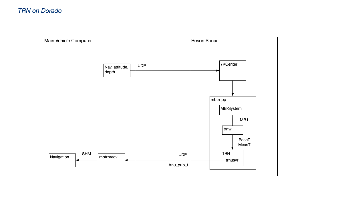
mbtrnpp subscribes to sonar data streams via 7KCenter (sonar vendor application). Navigation and attitude data are injected into the sonar data stream. mbtrnpp parses, validates, and filters the data stream, and generates an MB1 record with each sounding (sonar ping). The libtrnav trnw library (TRN C wrapper API) is used to convert the MB1 records to PoseT and MeasT records, provided as motion and measurement updates.
mbtrnpp checks the return value of the motion/measurement updates and if successful, requests a position estimate using TerrainNav::estimatePose. The estimate is published using a trnu_pub_t message (also part of the trnw library). The Dorado main vehicle computer, a subscriber to the TRN updates, passes the offset to the vehicle navigation, which may optionally apply it.
Previously, Dorado used trn-server (TCP network TRN instance), rather than mbtrnpp. In that configuration (sometimes referred to by the developers as "classic TRN"), navigation/attitude and bathymetry inputs would be marshaled by TerrainAidDriver on the main vehicle computer (MVC), and a TerrainNavClient would interact with the trn-server. In that case, little or no filtering was applied.
Application: MBARI Long Range AUV (LRAUV)
LRAUV-TRN Architecture
The TRN application to support Long Range AUV (LRAUV) navigation (LRTRN) is very similar in architecture to the original developmental version of TRN for Dorado-class vehicles used successfully in the mid to late 2010s. LRTRN contains a single embedded instance of the TerrainNav class that implements the core capabilities of TRN. LRTRN receives data from the LRAUV main vehicle computer (MVC) and calls the TerrainNav instance directly. There are no servers in the architecture, but a server could be substituted in place of the embedded instance.
LRTRN runs on the LRAUV backseat computer (BSC). The BCS is an embedded Linux system that can be powered on and shutdown by the MVC depending on the mission. Communication between the MVC and BCS systems is handled exclusively through LCM channels. As of this writing the BCS is a NVIDIA Jetson Nano running Ubuntu. LRTRN is setup as a system service and starts when the BCS is booted.
LRTRN requires a single parameter specifying the location of the LRTRN configuration file (CFG) on a local filesystem. The first action of LRTRN is loading the CFG which consists of these main sections:
- ‘ops’ section - specifies the UTM zone in which the vehicle will operate
- ‘lcm’ section - settings for LCM communication, i.e.:
- URL used for LCM multicast communication
- Timing settings used for handling LCM messages in coherent groups
- Channel settings specify the message channel names and the message field names used to fill the poseT and measT inputs to TRN
- ‘trn’ section - settings for TRN operation, i.e.:
- Type of sonar instrument (DVL only workable option)
- TRN timing period (time between TRN I/O updates, e.g., 4 seconds)
- Map file name and map type (e.g., PortTiles)
- Traditional TRN top-level configuration file name (e.g., LRAUV_specs.cfg)
- TRN filter type weighting options (e.g., Particle filter)
After CFG is loaded LRTRN instantiates a TerrainNav object and an LCM context using the settings in CFG. When successful, LRTRN simply begins listening for LCM input messages. The data in the messages are used to populate the usual poseT and measT objects that drive the TRN processing. These LCM messages normally come from the MVC during actual missions, but they can also originate from simulations and log file players that are often used to test LRTRN by republishing logged data or logged LCM messages.
Dataflow
As previously mentioned, LCM is used for all communication between the MVC and BCS. That means LCM message channels drive all of the I/O for LRTRN and the embedded TerrainNav instance. The diagram below illustrates dataflow between the two systems.
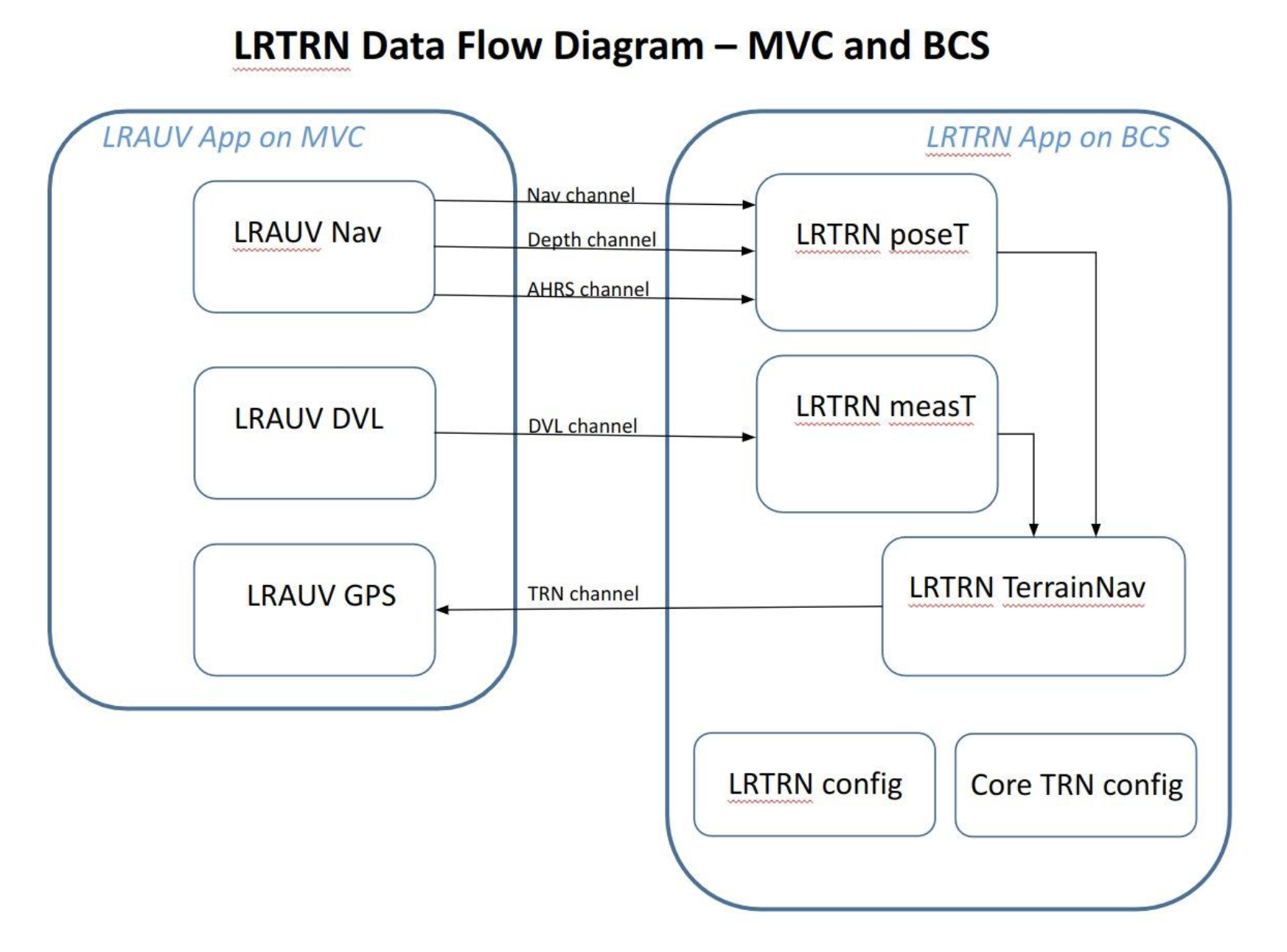
LRTRN receives vehicle state and sonar messages at the nominal MVC control system rate (e.g., 2.5 Hz or 400 ms period) LRTRN publishes updated TRN position estimates at the rate configured in CFG (typically 0.25 Hz or 4 second period). The lrauv-lcmtypes message format is used for all LCM channels.
The lrauv-lcmtypes type message structure contains a timestamp field when the message is sent from the publishing system. The timestamp in messages from the MVC is used as the timing clock in LRTRN processing. The MVC system time is essentially imported into LRTRN via the LCM input messages as a way to synchronize the LRTRN and MVC control system processes. This means the data in both processes is timestamped with the same clock. This timing architecture has a number of benefits including removal of system clock differences and the ability to run tests and simulations faster than real time.
Processing Overview
Refer to the dataflow diagram above for a visual reference to the discussion in this section.
Initialization
Processing begins with the initialization phase. The application starts by loading the configuration file specified in the sole command line parameter. The configuration file specifies all the processing options for the LRTRN application. If the file cannot be loaded or any subsequent files fail to load, the application will fail straight away. Otherwise the application is ready to go. Initialization is outlined below.
- Load LRTRN configuration file (CFG)
- Failure to locate or properly load the file results in immediate termination
- LCM section contains all the channel and message item names as well as the LCM message handling timing attribute (see related item in Application Notes section of this document below)
- TRN section contains the legacy TRN settings and options. For example:
- Core TRN vehicle configuration file - e.g., LRAUV_specs.cfg
- Measurement instrument type and number of beams
- Map file name - e.g., PortTiles
- Filter option - e.g., Particle Filter, Point Mass Filter, etc.
- Weighting option
- Dead Reckoning - default value is true; false value used for testing in piggyback mode
- Load TRN map and core TRN configuration file specified in CFG
- Failure to load results in immediate termination
- Create TerrainNav object used for TRN calculations
- Apply TRN configuration options to the TerrainNav object
- Create LCM context
- Match message handling functions with channel names
- Listen for LCM messages for TRN inputs
Main loop
The main loop runs continuously until the program is halted. The steps taken in the loop are outlined below.
-
Messages received from the Navigation, AHRS, and Depth channels are used to update
the active poseT object
- Message received as part of a burst that occurs at the control system frequency
- The messages from the MVC are all of the type lrauv-lcmtypes
- The timestamp item of these messages update the applications’ internal TRN-clock
-
Messages received from the DVL channel are used to update the active measT object
- Message received as part of a burst that occurs at the control system frequency
- The messages from the MVC are all of the type lrauv-lcmtypes
- The timestamp item of messages update the applications’ internal TRN-clock
-
Periodically call the motion and measurement update functions of the TerrainNav object
- The period is specified in the TRN section of the CFG file (e.g, 4 seconds)
- The internal MVC-driven clock is compared to the previous update time to determine if the period has expired
-
Periodically publish the current TRN estimates obtained by calling the estimate functions of the TerrainNav object
- Same period as the motion and measurement updates (e.g., 4 seconds)
- The TRN channel name is specified in the LCM section of CFG
-
The MVC system closes the control loop on TRN by treating the TRN position estimate
as a GPS fix
- LRTRN publishes the position estimate by taking the dead-reckoning position of the vehicle, adding the offset calculated by TRN, and returning the result as latitude, longitude, and depth
- TRN estimate includes a set of confidence values called covariances
- The MVC can accept the TRN estimate as a GPS fix when the covariances lower to a certain limit
Closing The Loop on the TRN estimate
As discussed in the Main Loop section above, LRTRN publishes the estimated vehicle position from TRN to the MVC. After every motion and measurement update provided to TRN during a mission TRN also updates an internal vehicle position estimate along with a set of covariances that represent the relative confidence level in the estimated values. The estimate can be accepted by the MVC as a GPS fix when the covariances of the northing and easting TRN position estimates fall below a certain threshold. Traditionally, the calculation used is:
acceptable = sqrt[ (covarN*covarN) + (covarE*covarE) ] < THRESHOLD
Lower covariance values mean higher confidence. Likewise, a lower threshold value is more stringent in that it requires more confidence in the TRN estimates. A threshold value of 7 is commonly used.
The decision to use the TRN estimate as a GPS fix in the MVC is a departure from the original usage when TRN was developed. For TRN to perform calculations correctly the input to TRN motion updates (i.e., the change in vehicle position) need to be the consistent dead-reckoned (DR) position of the vehicle, not the TRN-corrected position. The GPS fix provided by TRN produces a tear in the navigated position that would immediately confuse TRN if used as the vehicle position in the next motion update. To avoid this issue, LRTRN internally maintains the DR position of the vehicle to use for motion updates for TRN. This DR position is the input for TRN motion updates.
Application Notes
Bursty LCM Message Handling
The MVC control system calculates and updates the vehicle state and publishes this data in a quick burst of messages at the end of every control cycle. To receive these messages using LCM the programmer subscribes to the named message channels by specifying a local message handling function. A call to an LCM handle function on the receiving system causes LCM to listen for traffic on any one of the subscribed channels. LCM calls the corresponding message handling function when a message is received on a subscribed channel.
In LRTRN we use the handleTimeout(ms) function that returns control back to the caller either when a message is handled or a timeout has expired. It is important to note that when LCM does detect traffic on any channel it returns immediately after the handling that first message. In other words, LCM handles only one message at a time (or none if the timeout has expired).
This message exchanging arrangement introduces an issue in the LRAUV-LRTRN architecture because the MVC uses more than one channel to communicate the state of the vehicle (e.g., Nav, AHRS, DVL, etc.) at the control frequency. Put simply, the LRTRN application will work best if it uses a coherent dataset from the vehicle that was calculated in the same period rather than mixing results from consecutive control cycles. To acquire a coherent dataset LRTRN employs a simple two-mode burst timing strategy to handle LCM messages using two settings in the configuration file: initial-timeout and max-timeout.
LRTRN first uses handleTimeout(initial-timeout) until the first message in a burst is handled. The pseudocode below is for illustration. Assume values of 50 ms for initial-timeout, 100 ms for max-timeout, and 10 ms for nominal-timeout.
// Do nothing until a burst is detected
while (0 == LCM.handleTimeout(initial-timeout)) ;
When a message is handled by LCM the method returns 1 and we assume that was the first message of the incoming burst (this may not be true for the very first burst at startup). LRTRN then moves on to the second stage of the strategy by letting LCM continue to handle messages until the burst is complete:
// Handle messages until max-timeout has expired
while (false == expired(max-timeout)) {
LCM.handleTimeout(nominal-timeout);
}
Usage over the years have demonstrated this to be a simple and effective strategy to quickly detect and consistently home-in on message bursts from the MVC control system. Tests also confirmed that, although TRN will still converge without this burst adaptation, the convergence takes longer and is not as crisp as when using the timing. Or, what one would expect when receiving noisy input data. Observations also show the message bursts usually last less than 50 ms and gaps between bursts are consistently over 300 ms. The burst timing settings can be changed to accommodate faster or slower than real-time message traffic by either reducing or increasing the timeout values.
LRAUV LCM Types
LRTRN makes use of the LRAUV LCM library type known as lrauv-lcmtypes. It is a sort of one-size-fits-all generalized LCM type used to communicate with the MVC. It was developed to halt the spread of application-specific LCM data types and the associated maintenance. The message type is an LCM version of a hash-table, or map, that can be used to define message structures dynamically. Message fields are retrieved using a string name and by calling access function based on C-types. As an example:
// This is code inside of an LCM message handler.
// Assume msg is a lrauv-lcmtype message.
Float timestamp = msg.getFloat(“Timestamp”);
The benefit of using this class is that the LRAUV engineers need only use this one generalized LCM type. The drawback is that much more code is required to set up messages and access fields in those messages. In the LRTRN application you will see a lot of repetitive lines of code that deal with initializing these messages. Source files can become rather verbose, but it’s an understandable tradeoff.
Application: MBARI ROV Ventana/LASS
In the ROV context, TRN is currently being developed; it is primarily motivated by locating the vehicle to a map for repeat surveys of specific features and sites. Doing so efficiently increases potential observing time.
On the ROV, TRN sensor data streams are distributed (pub/sub) and logged using the LCM (lightweight communication and marshaling) middleware library here; the LCM input processing, variable sensor suite, and unique TRN architecture form an interesting implementation.
The ROV is frequently reconfigured for different types of missions. The available senors may change, but bathymetry, attitude, and navigation are virtually always present. Some payloads include their own, for example the Low Altitude Survey System (LASS), a tool sled which carries LIDAR, multi-beam sonar, cameras and an INS for centimeter scale mapping. Some LASS instrumentation is mounted an articulating surface, which pivots to accommodate changes in terrain (e.g. cliff walls).
The libtrnav trnxpp application (opt/rov) implements the sensor input and TRN front-end. trnxpp introduces the concept of a TRN context:
- a set of inputs associated with
- a plug-in processing module
- a TRN instance (which may be a trn-server, mbtrnpp instance, etc.)
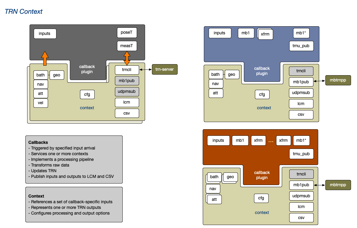
The basic architecture of trnxpp is shown in the figure below.
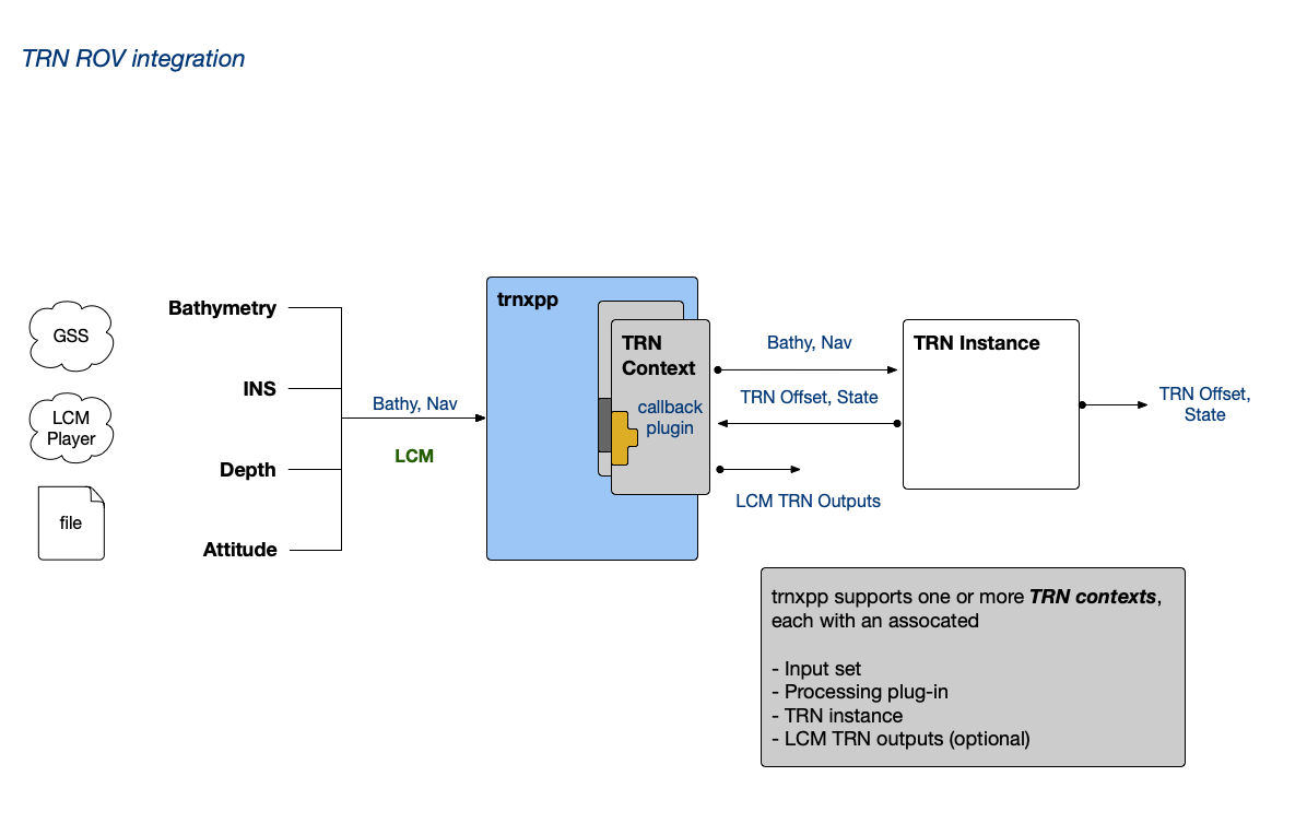
So, trnxpp may be configured to use the available sensor suite. For example if multibeam sonar is available, mbtrnpp may be used as the TRN instance, whereas trn-server may be used with a DVL bathymetry source.
trnxpp can support multiple contexts, though typically only one is used.
All data inputs arrive asynchronously via LCM. An input stream may provide multiple parameters, for example navigation, attitude, and/or velocity. libtrnav opt/rov package includes logic for receiving and validating LCM message data, and presenting them via generic interfaces by type (bathymetry, navigation, attitude, velocity, etc.).
The context processing callback plug-in operates on a specific set of input types (not specific sensors), which may include multiple sources for the same type. Context processing is initiated by the arrival of a designated trigger input (e.g. bathymetry). Upon arrival, the context processing callback is invoked, and the other required data inputs, which are also being updated asynchronously, are sampled and validated. Incoming data streams are queued (depth configurable) to enable interpolation; typically the sample from each input is used.
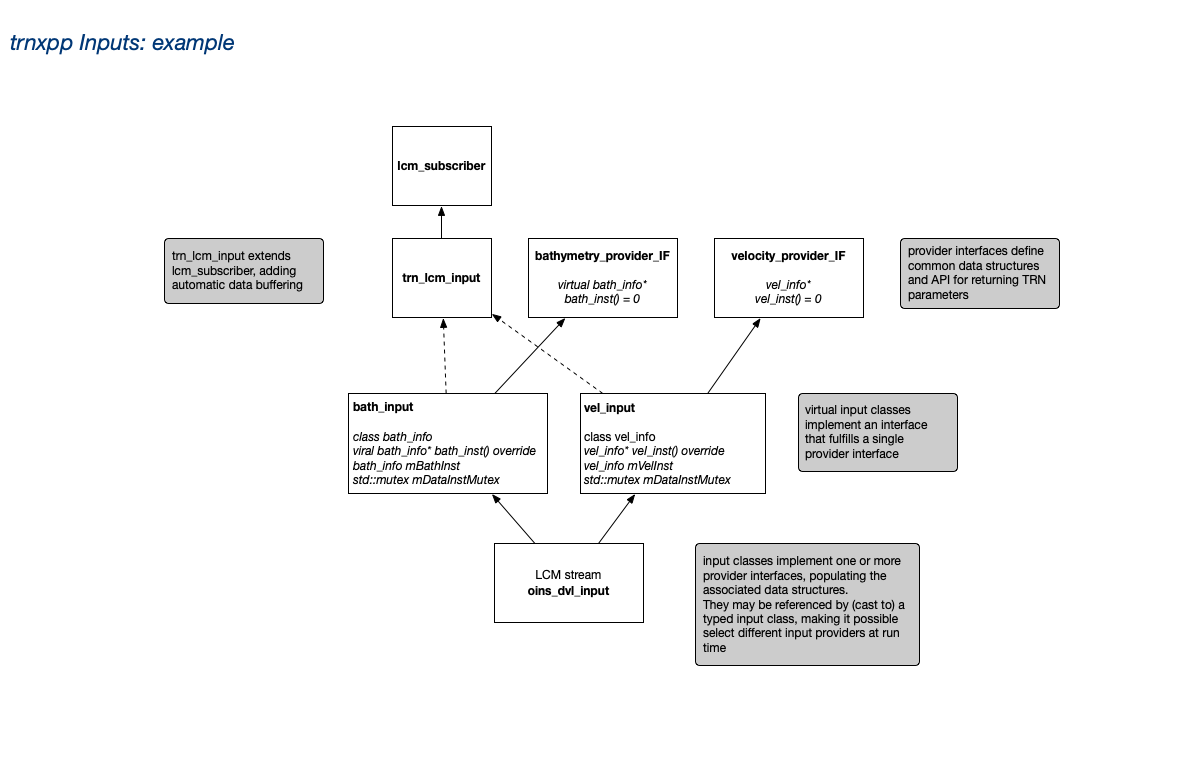
In some applications, for example when sensors able to move relative to the vehicle frame of reference, processing plug-ins require geometry information to resolve bathymetry beam components in the vehicle or world inertial frame. To that end the libtrnav opt/rov package defines some configuration semantics along with parsing and data structure classes to enable these to be defined at configuration time.
Application: WHOI Sentry
TRN for the WHOI Sentry vehicle is similar to the Dorado architecture. There, mbtrnpp (with its embedded TRN instance) is run on an x86 64-bit Ubuntu Linux backset computer. Recent surveys at Axial Seamount have used the Kongsberg EM 2040 multibeam sonar or the Reson T50. Both sonars support ancillary data integration with navigation and attitude streams.
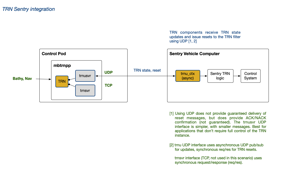
Sentry uses the libtrnav trnu_cli component class to interact with the mbtrnpp trnusvr interface. trnu_cli may be used to receive updates synchronously (req/res) or asynchronously (pub/sub); this is demonstrated in the trnu-cli utility. On Sentry, the asynchronous pub/sub is used to receive TRN updates, and offsets are passed to Sentry's control system via some intermediate logic.
trnu_cli is also used to request TRN filter resets. TRN resets may be triggered in software or manually using acoustic comms. trnu_cli sends UDP reset requests to the mbtrnpp trnusvr, which uses a callback in mbtrnpp to perform the reset.
The trnusvr interface supports only the TRN reset API.
TRN Software Appendices
- TRN Software Appendices
Appendix: trnplayer-sandbox.sh
Download and build a sandboxed installation of libtrnav with trn-player
#!/bin/bash

# Default canfiguration
SESSION=$(date +%Y%m%d_%H%M%S)
MFRAME_BRANCH=master
LIBTRNAV_BRANCH=master
LIBTRNAV_DATA_BRANCH=main
PKG_NAME=pkg
STAGE_NAME=trnplayer
VERBOSE=N
KEEP_WORK=N

# set paths
BUILD_PARENT=$PWD

WORK_DIR=$BUILD_PARENT/trnplayer-$$
MFRAME_BUILD=$WORK_DIR/mframe/build
MFRAME_INSTALL=$MFRAME_BUILD/$PKG_NAME
LIBTRNAV_TOP=$WORK_DIR/libtrnav
LIBTRNAV_BUILD=$WORK_DIR/libtrnav/build
LIBTRNAV_INSTALL=$WORK_DIR/sandbox
LIBTRNAV_DATA_BUILD=$WORK_DIR/libtrnav-data/build
LIBTRNAV_DATA_INSTALL=$LIBTRNAV_DATA_BUILD/$PKG_NAME

STAGE_DIR=$WORK_DIR/$STAGE_NAME

# function: verbose output
vout() {
    if [ $VERBOSE == "Y" ]; then
        echo $1
    fi
}

print_help() {
    echo ""
    echo " trnplayer-sandbox.sh : build trn-player binary distribution"
    echo ""
    echo " Use: trnplayer-sandbox.sh [options...]"
    echo " Options"
    echo ""
    echo "   -h : print help message"
    echo "   -k : keep working files"
    echo "   -v : enable verbose output"
    echo ""
}

# function: command line parser
parse_opts() {
    while getopts "hkv" opt ; do
      case $opt in
        h) print_help
            exit 1
        ;;
        v) VERBOSE="Y"
          ;;
        k) KEEP_WORK="Y"
          ;;
        :) # Catch missing arguments for options that expect one
          echo
          echo "Error: Option -${OPTARG} requires an argument." >&2
          echo
          print_help
          exit 1
          ;;
        ?) # Catch invalid options
          echo
          echo "Error: Invalid option -${OPTARG}." >&2
          echo
          print_help
          exit 1
          ;;
        esac
    done
}

# get command line options
parse_opts $*

# show config (verbose)
vout "VERBOSE $VERBOSE"
vout "KEEP_WORK $KEEP_WORK"

# make working directory
vout "mkdir $WORK_DIR"

mkdir -p $WORK_DIR

# clone, build install libtrnav
vout "cloning mframe..."

cd $WORK_DIR
git clone git@bitbucket.org:mbari/mframe.git

vout "building mframe branch ${MFRAME_BRANCH}..."

cd mframe
git checkout ${MFRAME_BRANCH}
mkdir build

cd build
cmake -DCMAKE_INSTALL_PREFIX=$MFRAME_INSTALL ..
cmake --build .
cmake --install .

# clone, build install libtrnav
vout "cloning libtrnav..."

cd $WORK_DIR
git clone git@bitbucket.org:mbari/libtrnav.git

vout "building libtrnav branch ${LIBTRNAV_BRANCH}..."

cd libtrnav
git checkout ${LIBTRNAV_BRANCH}
mkdir build

cd build
cmake -DCMAKE_INSTALL_PREFIX=$LIBTRNAV_INSTALL -DCMAKE_PREFIX_PATH=$MFRAME_INSTALL ..
cmake --build .
cmake --install .


#  clone libtrnav-data into staging directory
vout "cloning libtrnav-data branch $LIBTRNAV_DATA_BRANCH in $LIBTRNAV_INSTALL..."

cd $LIBTRNAV_INSTALL
git clone git@bitbucket.org:mbari/libtrnav-data.git

cd libtrnav-data
git checkout $LIBTRNAV_DATA_BRANCH

vout "running post-install..."
for APP in $(ls $LIBTRNAV_INSTALL/bin/*)
do
# change netcdf library load path to use RPATHs
# to make it relocatable
install_name_tool -change /opt/local/lib/libnetcdf.22.dylib @rpath/libnetcdf.dylib $APP

# codesign executable so it won't be rejected by SIP/Gatekeeper
codesign --force --deep --sign - $APP
done

if [ ${KEEP_WORK} == "N" ] ; then
    vout "removing mframe..."
    rm -rf $WORK_DIR/mframe
    vout "removing libtrnav..."
    rm -rf $WORK_DIR/libtrnav
fi

vout "libtrnav installed: $LIBTRNAV_INSTALL"
vout "done"
Appendix: trn-player Configuration File Reference
Syntax
- key = value pairs
- leading/trailing whitespace OK
- supports terrainAid.cfg and/or trn-player options
- semicolon terminations (terrainAid.cfg) optional
- comments may start with '#' or '//''
- environment variables using $[A-Za-z0-9_-.] (no braces) will be expanded
trn-player Options
  Option  : Description
 ----------------------------------------------------------------
 cdir     : config directory
 config   : config file path
 ddir     : data directory
 dperiod  : decimation period (ms) alias: samplePeriod
            >0  : Decimates records to match specified
                  input period as nearly as possible
            <=0 : Disabled (use all records)

 eofile   : estimate output file name (w/o path)
 ftype    : TRN filter type
              0: TRN_FT_NONE
              1: TRN_FT_POINTMASS
              2: TRN_FT_PARTICLE (default)
              3: TRN_FT_BANK
              values other then 2 are experimental

 fstat    : force beam status true (TerrainNav.log)
 oflags   : output flags (may include multiple)
              p: pretty
              m: measurement CSV
              e: estimate CSV
              q: quiet
              S: output MMSE
              L: output MLE
              B: output both MLE, MMSE

 interp  : map interpolation method (DEM maps only)
              0: nearest-neighbor (no interpolation)
              1: bilinear
              2: bicubic

 iformat : input format
              0: MbTrn.log
              1: TerrainNav.log
              2: TerrainAid.log
              3: DVL CSV [1,2]
              4: IDT CSV [1,2]
              5: MB/Generic CSV [1,2]

              [1] implies moformat = iformat; use -Z --moformat to override
              [2] no default name; use -O, --mofile to set/enable

 ifile    : log/input name (override lookup based on type)
 mdir     : map directory
 mfile    : map file name (w/o path)
 odir     : TRN output directory
 mofile   : measurement output file name
 pfomode  : particles file logging mode
              0: HISTOGRAM (distribution summary)
              1: PARTICLES (all particles; large data volume)

              log full particle states or a histogram
              Note: generates a large volume of data
              writes to odir/filterDistrib.txt

 pfile    : particles file name (w/o path)
 reinits  : allow TRN particle filter reinits
 stype    : Bathymetry data format passed to
            measurement update; may differ from sensor of origin
            Corresponds to terrainAid.cfg sensor_type
              0: UNDEFINED
              1: TRN_SENSOR_DVL    DVL
              2: TRN_SENSOR_MB     Multibeam
              3: TRN_SENSOR_PENCIL Single Beam
              4: TRN_SENSOR_HOMER  Homer Relative Measurement
              5: TRN_SENSOR_DELTAT Imagenex DeltaT

 vfile    : vehicle spec file name (w/o path)<
 mweight  : set modified weighting scheme
              0: TRN_WT_NONE No modification
              1: TRN_WT_NORM  Shandor's original alpha modification
              2: TRN_WT_XBEAM Crossbeam with original
              3: TRN_WT_SUBCL Subcloud with original
              4: TRN_FORCE_SUBCL Force Subcloud every measurement
              5: TRN_WT_INVAL Force invalid

 mtype    : map file format
              0: UNDEFINED
              1: TRN_MAP_DEM Digital Elevation Map (.GRD)
              2: TRN_MAP_BO  Binary Octree Map (.BO)

 moformat : measurement output CSV file format (input file format enum)
              Use -Z, --moformat to override default (== iformat)
              i.e. to convert DVL, IDT to MB/Generic format

              No default name

              Use -Z, --mofile to enable measurement output, set file name

Defaults:

 - sensor   : TRN_SENSOR_MB
 - mfile    : PortTiles
 - vfile    : mappingAUV_specs.cfg
 - ifile    : Mbtrn.log
 - mdir     : ./maps
 - cdir     : ./data
 - ddir     : ./data
 - iformat  : IOFMT_MBTRN
 - oflags   : pS
 - odir     : trnplayer[-TRN.n]
 - moformat : same as input format for CSV input; IOFMT_MB otherwise
 - eofile   : none
 - mofile   : none
terrainAid.cfg Options
 Option               : Description (trn-player alias)
 ----------------------------------------------------------------
 mapFileName          : map file name (mfile)
 particlesName        : particles file name (pfile)
 vehicleCfgName       : vehicle spec file name (vfile)
 dvlCfgName           : DVL spec file name
 resonCfgName         : Multibeam spec file name
 lrauvDvlFilename     : LRAUV DVL spec file name
 map_type             : TRN map format (mtype)
 filterType           : TRN filter type (ftype)
 allowFilterReinits   : allow TRN filter reinitializations if true (reinits)
 useModifiedWeighting : use modified weighting scheme (mweight) [1]
 mapInterpMethod      : map interpolation method (interp)
 forceLowGradeFilter  : Use low grade filter (flgf) [2]
 terrainNavServer     : trn-server host IP address
 terrainNavPort       : trn-server host IP port
 samplePeriod         : decimation period (msec) (dperiod)
 maxNorthingCov       : TRN convergence criteria
 maxNorthingError     : TRN convergence criteria
 maxEastingCov        : TRN convergence criteria
 maxEastingError      : TRN convergence criteria
 RollOffset           : roll angle (phi) bias (deg)
 useIDTData           : process as IDT
 useDVLSide           :
 useMbTrnData         : use MbTrn log
 useMbTrnServer       : use MbTrn server

 Notes:
 [1] Modified Weighting:
     pmf grid resolution is specified in the ones digit as follows (0 to 5)
      0 == default
      1 == 1
      2 == 2
      3 == 3
      4 == 4
      5 = 0.5
     Examples:
      use == 125, grid res == 0.5
      use == 123, grid res == 3
     Number of filters is calculated using the 10's digit
     as follows (0 to 5)
      0 == default
      1 == 1
      2 == 2
      3 == 4
      4 == 10
      5 == 11
     pmf grid size is specified using the 100's digit
     as follows (0 to 2):
      0 == 100
      1 == 200
      2 == 300
     Examples:
      useModifiedWeighting = 15;  1  Numfilt=1, Pmf grid .5m
      useModifiedWeighting = 11;  2  Numfilt=1, Pmf grid 1 m
      useModifiedWeighting = 21;  3  Numfilt=2, Pmf grid 1 m
      useModifiedWeighting = 51;  4  Numfilt=11,Pmf grid 1 m
      useModifiedWeighting = 41;  5  Numfilt=10,Pmf grid 1 m

 [2] forceLowGradeFilter:
      if true,filter performs angular rate
      integration and estimates attitude and position.
      if false, filter will choose its settings based on
      the kearfott system is available.
Appendix: Example mbtrnpp.cfg
SeafloorMapping/2024/AxialSeamount/TRN/TRNtest/0_TRNconfig/mbtrnpp-sentry.cfg
#  mbtrnpp configuration
#  [generated by mbtrncfg]
#
# - option naming same as command line (w/o '--')
# - use '#' or '//' for comments
# - "opt" annotations indicate option name and internal type
    # - some options support variable substitution:
    #     option        variable          description
    #     ------        --------          -----------
    #     output        SESSION           mbtrpp session ID (YYYYMMDD-hhmmss)
    #     input         TRN_RESON_HOST[1] input socket IP address
    #     mb-out        TRN_HOST[1]       TRN processing host IP
    #     trn-out       TRN_HOST
    #     trn-mid       TRN_SESSION       TRN mission ID (YYYY-JJJ) (JJJ: year day)
    #     log-directory TRN_LOGFILES[2]   TRN log directory
    #     trn-map       TRN_MAPFILES[2]   TRN map file directory
    #     trn-par       TRN_DATAFILES[2]  TRN data/cfg file directory
    #     trn-cfg       TRN_DATAFILES
    #   Notes
    #     [1] use current host IP address if environment unset
    #     [2] use current directory if environment unset

// opt verbose [int]
// debug output level
// <0 : TRN debug (-2 typical)
// >0 : MB-System debug (>2 very verbose)
verbose=0

// opt log-directory [mb_path]
// log directory
log-directory=mbtrnpp-SESSION

// opt input [input_mode_t]
// input data source specifier
// file_path
// socket:IP:port:bcast_group
input=socket:TRN_RESON_HOST:239.255.0.1:6020

// opt format [int]
// input data format
format=261

// opt auv-sentry-em2040 [none]
// enable special pressure depth encoding in Sentry EM2040
auv-sentry-em2040

// opt output [?]
// output mode specifier
output=file:mbtrnpp_SESSION.mb1

// opt swath-width [double]
// sonar swath (decimal degrees)
swath-width=90

// opt soundings [int]
// number of sonar soundings to output
soundings=21

// opt median-filter [?]
// median filter parameters
// <threshold>/<n_across>/<n_along>
median-filter=0.05/7/3

// opt platform-file [mb_path]
// description TBD
#platform-file=

// opt platform-target-sensor [int]
// description TBD
#platform-target-sensor=

// opt projection
// cartographic(?) projection ID
#projection=

// opt mbhbn [int]
// MB1 server heartbeat modulus
// (timeout preferred, use mbhbt)
#mbhbn

// opt mbhbt [double]
// MB1 server heartbeat timeout (s)
mbhbt=0

// opt trnhbt [double]
// TRN server heartbeat timeout (s)
trnhbt=0

// opt trnuhbt [double]
// TRNU (udp update) server heartbeat timeout (s)
trnuhbt=30

// opt delay [int64_t]
// Delay main TRN processing loop (msec)
delay=0

// opt statsec [double]
// TRN profiling logging interval (s)
statsec=30

// opt statflags [mstats_flags]
// TRN profiling flags
// MSF_STATUS - include status
// MSF_EVENT - include events
// MSF_ASTAT - include aggregated stats
// MSF_PSTAT - include periodic stats
// MSF_READER - include R7K reader stats
statflags=MSF_STATUS|MSF_EVENT|MSF_ASTAT|MSF_PSTAT

// opt trn-en [bool]
// opt trn-dis [bool]
// enable/disable TRN processing
// use Y/1: enable N/0: disable
trn-en=Y

// opt trn-utm [long]
// UTM zone for TRN processing (1-60)
// Monterey Bay : 10
//        Axial :  9
trn-utm=9

// opt trn-map [char*]
// TRN map file (required for TRN processing)
// (may be a directory path for tiled map)
trn-map=TRN_MAPFILES/AxialTiles2022

// opt trn-cfg [char*]
// TRN configuration file (required for TRN processing)
trn-cfg=TRN_DATAFILES/sentry_specs.cfg

// opt trn-par [char*]
// TRN particles file (optional for TRN processing)
#trn-par=

// opt trn-mid [char*]
// TRN mission ID
// (used for TRN log directory name prefix)
trn-mid=mb-TRN_SESSION

// opt trn-mtype [int]
// TRN map type
// TRN_MAP_DEM  1
// TRN_MAP_BO   2
trn-mtype=2

// opt trn-ftype [int]
// TRN filter type
// TRN_FILT_NONE       0
// TRN_FILT_POINTMASS  1
// TRN_FILT_PARTICLE   2
// TRN_FILT_BANK       3
trn-ftype=2

// opt trn-fgrade [int]
// filter grade
// 0: use low grade filter
// 1: use high grade filter
trn-fgrade=1

// opt trn-mweight [int]
// use modified weighting
// 0 - No weighting modifications
// 1 - Shandor's original alpha modification
// 2 - Crossbeam with Shandor's weighting
// 3 - Subcloud with Shandor's origina
// 4 - Subcloud with modified NIS always on
trn-mweight=4

// opt trn-ncov [double]
// TRN convergence criteria
// northing covariance limit
trn-ncov=49

// opt trn-nerr [double]
// TRN convergence criteria
// northing error limit
//trn-nerr=50
trn-nerr=500

// opt trn-ecov [double]
// TRN convergence criteria
// easting covariance limit
trn-ecov=49

// opt trn-eerr [double]
// TRN convergence criteria
// easting error limit
trn-eerr=500

// opt mb-out [?]
// MB1 output specifier
// comma delimited list including one or more of:
// mb1svr:<ip>:<port>  - enable MB1 server
// mb1                 - enable MB1 binary record logging
// file:<path>         - enable MB1 binary record logging
// file                - enable MB1 binary record logging (use default name)
// reson               - enable reson S7K frame logging
// nomb1               - disable MB1 binary record logging
// noreson             - disable reson S7K frame logging
// nomb1               - disable MB1 server
// nombtrnpp           - disable mbtrnpp message log (not recommended)
mb-out=mb1svr:TRN_HOST:27000,mb1r

// opt trn-out [?]
// TRN output specifier
// comma delimited list including one or more of:
// trnsvr:<ip>:<port>  - enable trn server interface
// trnu                - enable TRN update ascii logging
// trnub               - enable TRN update binary logging
// trnusvr:<ip>:<port> - enable TRN update server
// sout                - enable TRN output to stdout
// serr                - enable TRN output to stderr
// debug               - enable TRN debug output
// notrnsvr            - disable trn server interface
// notrnusvr           - disable TRN update server
trn-out=trnsvr:TRN_HOST:28000,trnu,trnusvr:TRN_HOST:8000

// opt trn-decn [int]
// TRN updpate decimation modulus
// (update TRN every nth MB1 sample)
trn-decn=1

// opt trn-decs [double]
// TRN updpate decimation interval (decimal seconds)
// (update TRN every dec seconds)
#trn-decs=3.0

// opt reinit-gain [none]
// enable/disable gating TRN resets using sonar transmit gain
reinit-gain

// opt reinit-file [bool]
// reinitialize TRN every time a new
// file is read when parsing a datalist
reinit-file=0

// opt reinit-xyoffset [double]
// reinitialize TRN whenever the magnitude of the
// lateral converged offset exceeds specified limit
reinit-xyoffset=0

// opt reinit-zoffset [double]
// reinitialize TRN whenever the converged z-offset
// is is outside specified range.
reinit-zoffset=-5.0/1.0

// opt covariance-magnitude-max [double]
// TRN convergence max covariance limit
covariance-magnitude-max=10

// opt convergence-repeat-min [int]
// TRN convergence minimum repeat limit
convergence-repeat-min=400
Appendix: Example mbtrnpp environment
SeafloorMapping/2024/AxialSeamount/TRN/TRNtest/0_TRNconfig/mbtrn-set-sentry.env
#!/bin/bash

# set environment for mbtrnpp
# see mbtrn/tools/mbtrn-cfg.example
# for decription of mnemonics and environment
# variables used in config file

# mbtrnpp socket input host multibeam host
# may be used in config file for socket input
# e.g. input=socket:TRN_RESON_HOST:7000:0
export TRN_RESON_HOST="192.168.100.130"

# TRN server host IP (IP of mbtrnpp host)
# may be used in config file for TRN outputs
# e.g. trn-out=trnsvr:TRN_HOST:28000,trnu,trnusvr:TRN_HOST:8000
export TRN_HOST="192.168.100.101"

# mbtrnpp binary directory
# used more for testing,
# switching between installed/build directory
export TRN_MBTRNDIR="/usr/local/bin"

# TRN server map file directory
export TRN_MAPFILES="$PWD/../0_TRNmaps"

# TRN server config file directory
export TRN_DATAFILES="$PWD/../0_TRNconfig"

# TRN server log file directory
# Not used logs can be made in the session directory
#export TRN_LOGFILES="/home/mappingauv/TRN/0_TRNlogs"
Appendix: mbtrncfg
The MB-System repository includes mbtrncfg, a browser-based TRN configuration tool.
mbtrncfg consists of a form to set configuration values, which may be downloaded to a configuration file. The mbtrncfg interface also generates an mbtrnpp command line with the selected settings, and has several presets which may be loaded.
Although it is specific to the MB-System TRN application, it may be useful as a template for other applications.
The source, a stand-alone web site, is located in MB-System/src/mbtrn/tools/mbtrncfg. To use mbtrncfg, open index.html in a web browser.
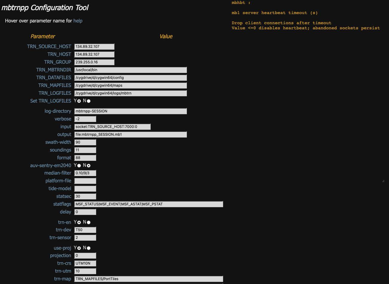
Fig: mbtrnpp options
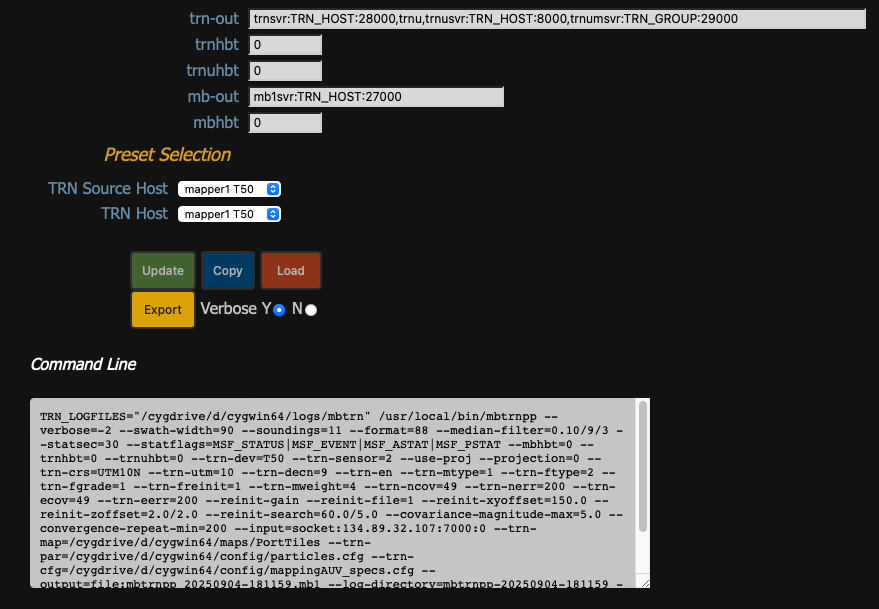
Fig: mbtrnpp controls
Appendix mbtrnpp-plot
The MB-System repository includes mbtrnpp-plot, a tool for generating plots from mbtrnpp log files. It uses qplot, a collection of bash scripts that extract CSV dataset subsets from mbtrnpp log files, and generate PDF plots using gnuplot, an open source plotting library. The plots are aggregated into a PDF file using ghostscript.
The plots generated provide status and performance information about a TRN session. For example, there are plots indicating when/where TRN was converged, changes in TRN state, TRN computation profiling, client connections and disconnections, and TRN output.
mbtrnpp plot output example may be viewed here
Although it is specific to the MB-System TRN application, mbtrnpp-plot may be useful as a template for other applications.
mbtrnpp-plot may be found in MB-System/src/mbtrn/tools/mbtrnpp-plot, and is documented in a README file there.
qplot is maintained in an MBARI bitbucket repo https://bitbucket.org/mbari/qplot.
Appendix: mframe
mframe may be built for linux, macOS, and cygwin/windows; the wrappers present a common API, and simplify instantiation and configuration.
libtrnav uses mframe components for a number of utilities.
Components
| Component | Description/th> |
|---|---|
| mappconfig | application (key/value pair) config |
| mbbuf | byte buffer |
| mcbuf | circular memory buffer |
| mconfig | library configuratio | mframe is a small C library consisting of lightweight, wrappers around commonly used code. Primarily, they are for IO (files, sockets, memory) and various containers and buffers. There are also a collection of debug macros (mxdebug) that enable per-module configuration, and that may easily compiled out if desired. Also, the module mstats enables the collection and use of performance metrics (counting events, e.g.).
| mdebug | debug output macros (deprecated, use mxdebug) |
| medebug | stderr debug output macros(deprecated, use mxdebug) |
| merror | error return and error string |
| mfile | file IO |
| mframe | core framework |
| mhash | dictionary/associative array |
| mkvconf | key/value configuration file reader |
| mlist | list container |
| mmdebug | per-module debug output macros (deprecated, use mxdebug) |
| mmem | reference-counted (mananged) memory allocation |
| mqueue | Wrappers for queue and list functions in sys/queue.h |
| mserial | serial IO |
| mstats | measure/log application statistics and metrics |
| mswap | byte swapping |
| mthread | pthreads wrappers |
| mtime | clocks, timers |
| mutils | utilities, e.g. bit set/test, formatted output (hex/binary, xml), string trim |
| mxdebug | per-module debug output macros |
Appendix: TRN Equations
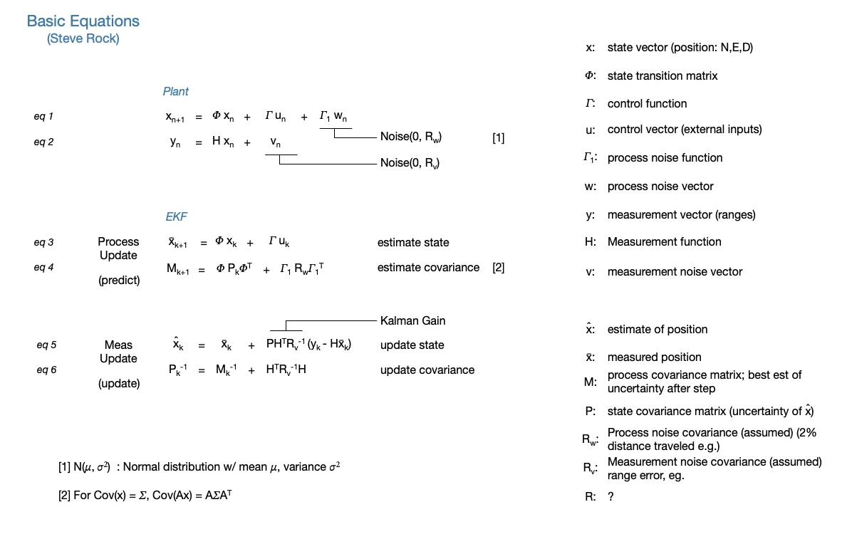
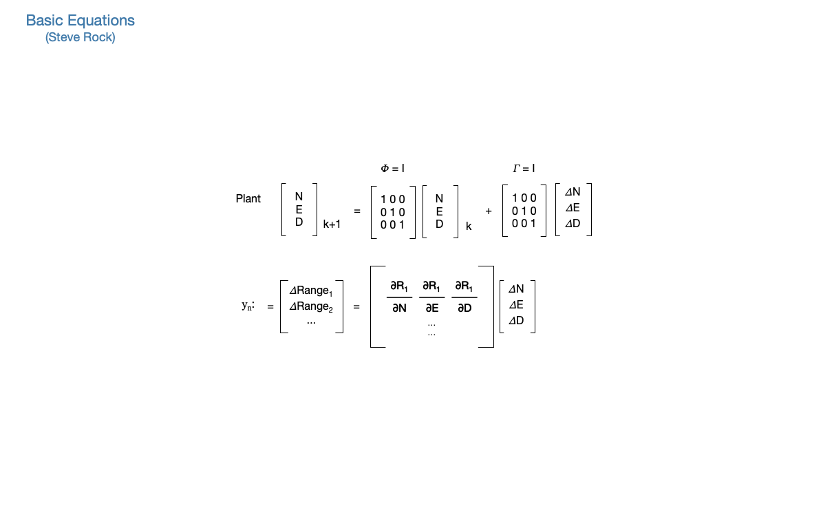
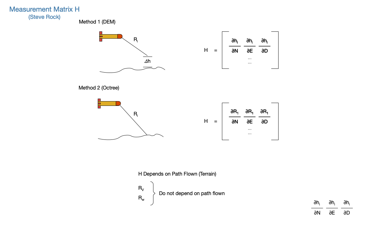


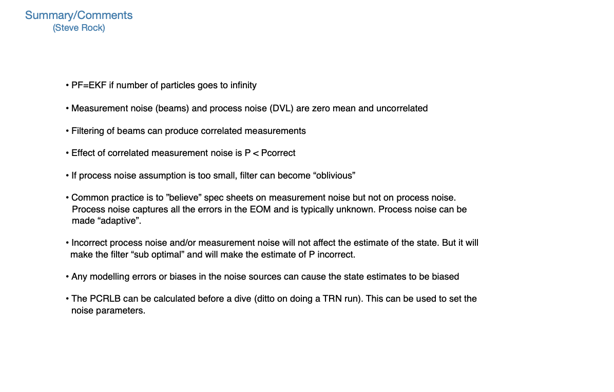
Appendix: Resources
| libtrnav | https://bitbucket.org/mbari/libtrnav | ||||
| mframe | https://bitbucket.org/mbari/mframe | ||||
| MB-System | https://github.com/dwcaress/MB-System
|
||||
| qplot | https://bitbucket.org/mbari/qplot | ||||
| LCM | https://github.com/lcm-proj/lcm |
Appendix: Terminology
| Term | Definition |
|---|---|
| CEP | circular error probability |
| Kalman Filter | |
| NED | North/East/Down |
| Particle Filter | |
| phi, theta, psi | euler angles, roll, pitch, heading |
| TRN | terrain relative navigation |
| u,v,w | body frame components |
| x,y,z | body frame axes |
| Eastings, Northings | coordinates in projection coordinate system |
| UTM | Universal Transverse Mercator projected coordinate system |
| LTM | Local Transverse Mercator projected coordinate system |
Appendix: Binary Octrees
MBARI/Stanford Terrain Relative Navigation (TRN) uses binary octree maps to represent bathymetry for ray-tracing. The basic concepts, data structures, and file formats used to represent binary octrees in software are described below.
Basic Properties
A binary octree is a data structure that represents space in discrete cubic elements that are somewhat analogous to the way that pixels are discrete units for a 2D space. A binary octree map represents a volume as a cube that is bisected into octants. Each octant (called a node) has a binary occupancy value, i.e. false (0) if it is empty, true (1) otherwise, and may be further bisected to create additional nodes of higher precision.
Octree maps inherently represent cubic regions in physical space, i.e. a cube with sides of S units.
The number of subdivisions is known as the octree depth; the physical extents of the tree, together with tree depth, determine the physical resolution of the octree. The number of nodes, N, is function of depth: \(N(d) = 2^(2d)\)
Logical extents (coordinates) are a function of depth: \(E(d)\ |\ 0:(2^d - 1)\)
Resolution (minimum feature size) is given by \(R(d) = S/2^d\)
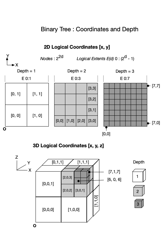
Fig: Binary octree coordinates, depth
Node Paths
A path data structure (also referred to as an index) is used in some computations that use octrees, e.g. ray tracing. A path consists of tuple of unsigned integers, representing the logical coordinates of a point. The path may be represented as single index value, in which the bits represent the coordinates at depths 0:d; the LSB represents depth=1, the MSB represents depth d.
The corresponding nth bits, taken as a tuple, form the logical coordinates at depth n.
In this example (using a quadtree, or 2D binary tree), the path corresponding to physical point (18,6) is calculated and the index computed.
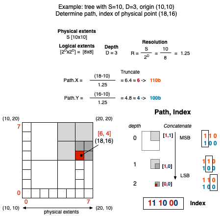
Fig: Example: Binary quadtree coordinates, indexing
Nodes
In the mapping context, boolean node values indicate occupied or unoccupied space. Since nodes represent regions with the same value, the number of nodes reflects the variability of the space represented by the map; however, a node must divided if the value of only one octant differs.
Octree nodes may be one of two types: a branch or leaf. Branches have no value, but contain child nodes that are either other branches or leaves. Leaf nodes have a single value (and no child nodes).
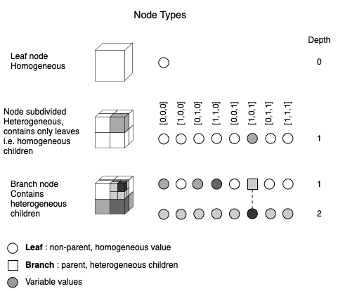
Fig: Binary octree node types
Ocean maps are typically constant at the top (mostly unoccupied, i.e. open water), and more variable at the bottom.
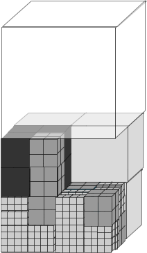
Fig: Binary octree ocean
Octrees contain less information in sparsely occupied regions, and so implement a form of 3D run length encoding compression.
Physical/Logical Mapping
The physical structure is mapped into file and logical structures as shown in the figure below. Note that the entries are arranged depth first; each node in the tree is a pair of values indicating occupancy and a boolean flag (hasChildren) indicating whether the node is a leaf (false) or branch (true). The first entry is the root node.
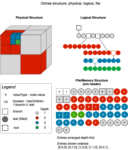
Fig: Binary octree structure
Indexing and Operations
For TRN, ray tracing is done to determine whether a point on the octree map is occupied, i.e. corresponds to a bathymetry measurement (beam).
Ray tracing and other operations on octrees that occur frequently in the mapping context include
- translating between physical and logical space
- calculating the file or memory index (offset) of a node
- finding a path (relative offset) between two nodes
The figure below shows how quadtree nodes are traversed using paths/indices described earlier. The process is similar for octrees.
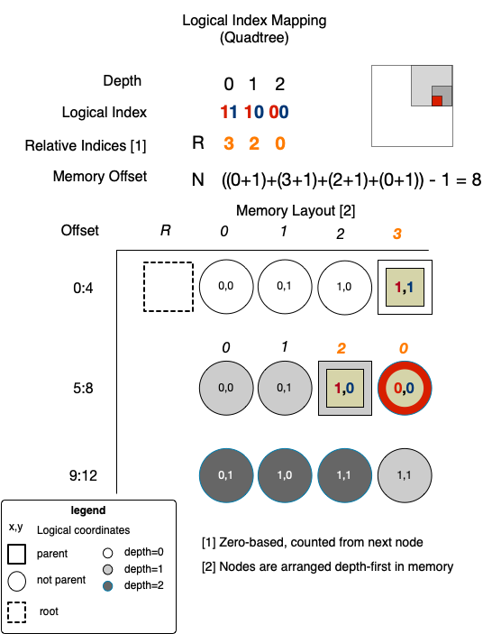
Fig: Quadtree index mapping
Another operation for finding the path to a node nearest to a point on a specified node and depth is explained below.
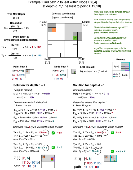
Fig: Example: Binary quadtree path calculation